68 MS 231, MS 231 C, MS 251, MS 251 C
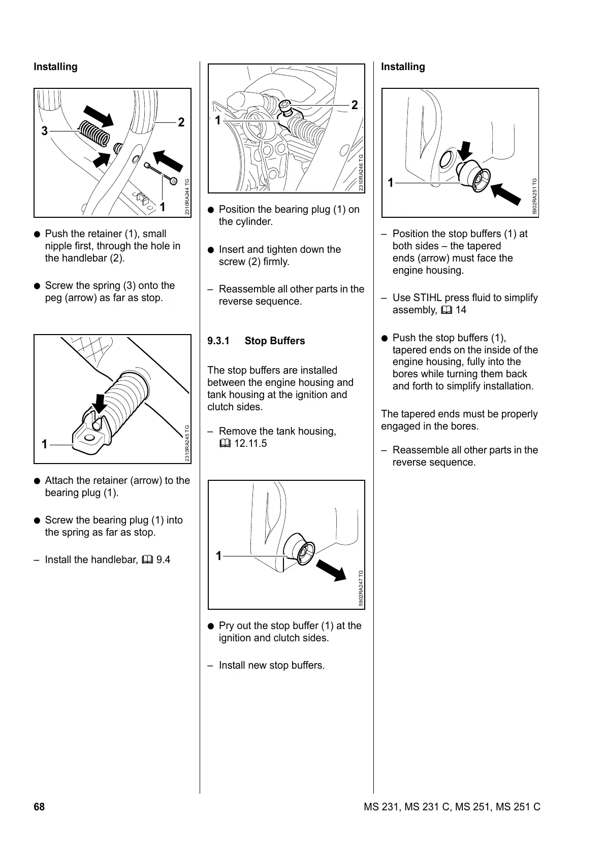
Installing
: Push the retainer (1), small
nipple first, through the hole in
the handlebar (2).
: Screw the spring (3) onto the
peg (arrow) as far as stop.
: Attach the retainer (arrow) to the
bearing plug (1).
: Screw the bearing plug (1) into
the spring as far as stop.
– Install the handlebar, b 9.4
2310RA244 TG
3
1
2
2310RA245 TG
1
: Position the bearing plug (1) on
the cylinder.
: Insert and tighten down the
screw (2) firmly.
– Reassemble all other parts in the
reverse sequence.
9.3.1 Stop Buffers
The stop buffers are installed
between the engine housing and
tank housing at the ignition and
clutch sides.
– Remove the tank housing,
b 12.11.5
: Pry out the stop buffer (1) at the
ignition and clutch sides.
– Install new stop buffers.
2310RA246 TG
2
1
5902RA247 TG
1
Installing
– Position the stop buffers (1) at
both sides – the tapered
ends (arrow) must face the
engine housing.
– Use STIHL press fluid to simplify
assembly, b 14
: Push the stop buffers (1),
tapered ends on the inside of the
engine housing, fully into the
bores while turning them back
and forth to simplify installation.
The tapered ends must be properly
engaged in the bores.
– Reassemble all other parts in the
reverse sequence.
5902RA251 TG
1
 Loading...