CryoTel® GT User’s Manual Version 6 P a g e | 16
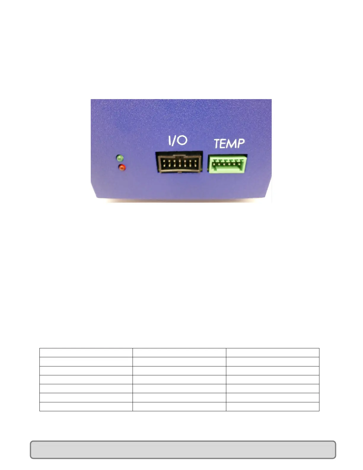
Digital Output 4 (I/O Connector pin 4) will go high (5V) when the cooler is at the set point temperature.
When the cooler is not at the temperature set point Digital Output 4 will be low (0V). See Figure 15 for
I/O connector pin out.
If both LEDs are flashing together repetitively, the controller is reporting an error. See Section XII for
details.
Figure 14: Controller LEDs
XII. Error Summary
If both LEDs are flashing together repetitively, the controller is reporting an error. There are two ways
to check the error codes. The ERROR<CR> command can be issued, or the number of LED flashes can be
counted.
When the ERROR<CR> command is issued, any errors that are present are indicated with a “1”. See
figure 15 for the error codes. Multiple error codes can be displayed simultaneously. For example a
return of “100001” would indicate an over current and temperature sensor error. See section XIII for
the serial communications reference.
To check and error code using the LEDs, count the number of flashes. Both the red and green LED will
flash simultaneously. There will be a series of short flashes followed by one long flash. The long flash
indicates the end of the sequence. The flash count includes both the short flashes and the long flash. If
there are multiple errors only one of them will be displayed by the LEDs, but after the long flash the red
and green LEDs will flash back-to back very rapidly.
Non-volatile Memory Error
Figure 15: Error Codes
 Loading...