CryoTel® GT User’s Manual Version 6 P a g e | 9
VII. Feedthroughs
The electrical pins on the metal plate at the end of the pressure vessel near the balance absorber are
surrounded by glass, which acts as an insulator and prevents helium from leaking out of the pressure
vessel. This arrangement is called a feedthrough. Because of the glass insulator, the feedthroughs should
be handled cautiously. They are a permanent feature of the pressure vessel back end plate and should
not be modified in any way.
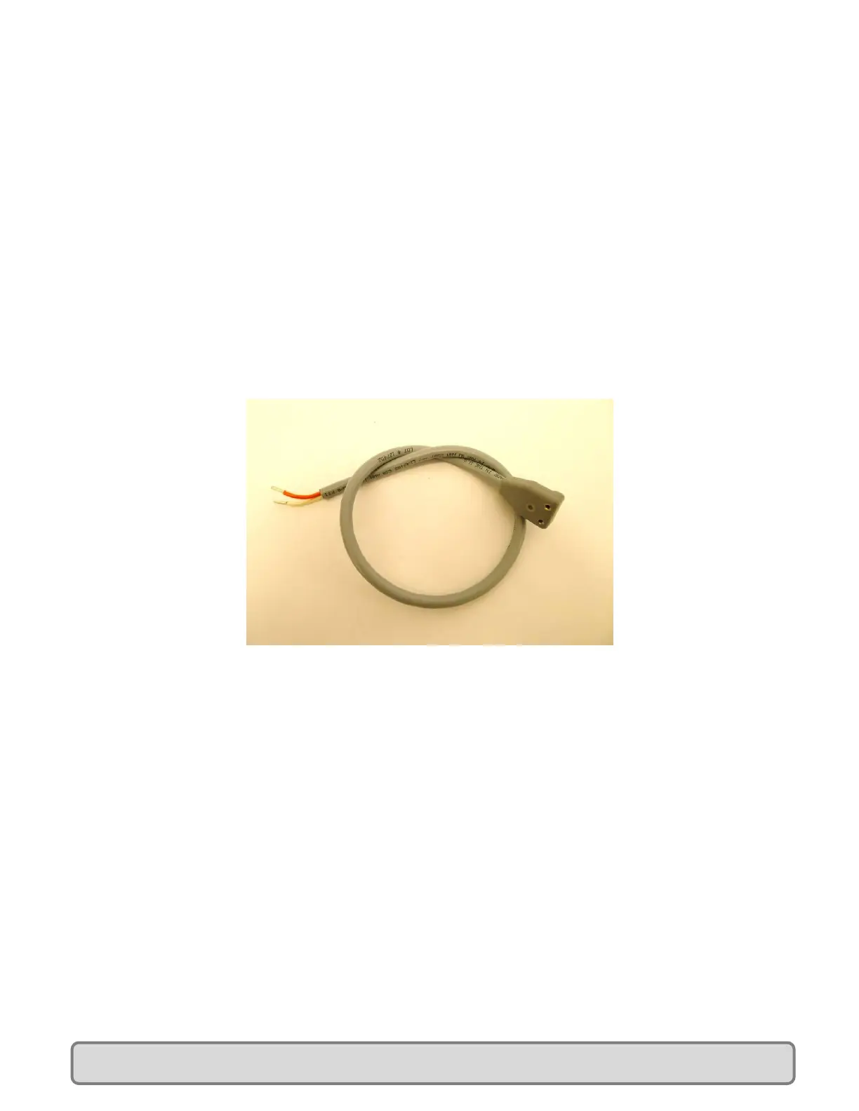
The CryoTel
®
GT is shipped with a power cable that attaches to the feedthroughs and the controller. This
cable consists of orange and white 16 gauge wires with a molded plastic connector for the feedthroughs
at one end and crimp sleeves to attach to the proper terminal block on the controller at the other end.
This harness is shown in Figure 6.
Figure 6: Power Cable
It is necessary to remove the balance absorber in order to install the power cable. The balance absorber
is attached with the center M5 screw. Remove this screw and the balance absorber will be free from
the cryocooler.
Install the power cable by aligning the cryocooler feedthrough pins with the holes in the cable connector
and pressing down. Insert the retaining screw into the connector and tighten.
Install the balance absorber by re-installing the M5 screw.
Important assembly notes:
The screw heads of the four balance absorber assembly screws need to be positioned so that none of
them are directly over either the power cord connector or the service tube elbow. This is to ensure that
the screw head does not impact either of these features during large amplitude displacements of the
balance absorber. See Figure 7 for details.
 Loading...