MOTOR INSTALLATION 3-27
ENGINE MOUNT
MOUNTING TO THE TRANSOM
DF25V2
Contained parts
Nut D: 40 N·m (4.0 kgf-m, 29.0 lb-ft)
NOTE:
•
Clamp bracket top side of two bolt holes is optional.
•
Drill the top holes at lest 25 mm(1.0 in) away from the transom top
surface.
• Drill the mounting holes vertically to the transom board.
• To ensure water-proofness, sealant should be applied to all bolt holes.
Apply the sealant to shanks of bolts, but not threads.
• Do not use an impact tool to tighten or loosen the transom nuts.
•
If tightening torque can not reach to the specified torque due to weak transom material, it is necessary to put the
transom board with an reinforcement plate between the transom board and the washer, to reinforce the tran-
som, contact the boat manufacturer as needed.
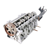
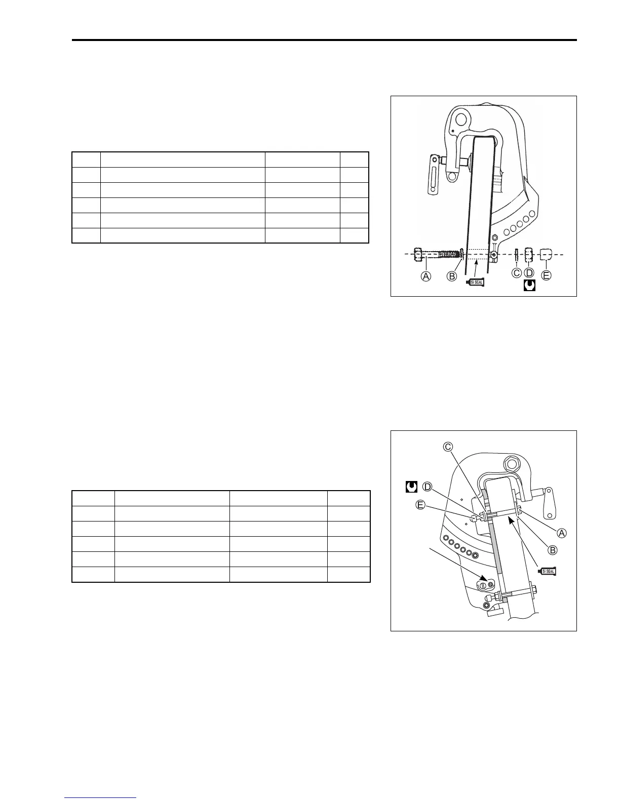
MOUNTING TO THE TRANSOM
DF25/30, DF40/50
Contained parts
Nut D: 55 N·m (5.5 kgf-m, 40.0 lb-ft)
NOTE:
• Drill the upper holes center at least 25 mm (1.0 in) away from
the transom top surface.
• For power trim & tilt model, drill the lower holes at the position
where the lower bolt does not interfere with the operation for
manual release valve.
• Install the large washer B on the transom board side.
• To ensure a water-tight engine installation, sealant (SUZUKI SILICONE SEAL or equivalent) should be
applied to all bolt holes.
• If tightening torque cannot reach to the specified torque due to weak transom material, it is necessary to
reinforce the transom board with an attachment plate.
Item Part name Part number Q’ty
A Bolt (M10 x 110 mm) 09100-10309 2
B Washer no.1 (Large)
35 x 10.5 09160-10139 2
C Washer no.1 (Small)
18 x 10.5 09160-10140 2
D Nut 09159-10050 2
E Cap 41153-95J00 2
Item Part name Part number Q’ty
A Bolt (12 mm) 09100-12093 4
B Washer (Large) 09160-12044 4
C Washer (Small) 09160-12110 4
D Nut 09159-12014 4
E Cap 41153-94500 4
Manual
release
valve

 Loading...