Electrical connections |
9
Position Description
5
Terminals for power supply of supply air fan
6
Terminals for internal relative humidity/temperature sensor
7
Analog input 1 — Outdoor air sensor
8
Analog input 2 — Supply air sensor
9
Analog input 3 — Freely configurable
10
Analog input 4 — Freely configurable / Overheat temperature sensor (units with
heater)
11
Analog input 5 — Freely configurable
12
Digital input 1 — Rotor guard sensor (VSR, VTR units)/ Damper signal (VTC units)
13
Digital input 2 — Freely configurable / Cooker hood (VTR 150/K unit)
14
Analog output 2 — Freely configurable / Electrical heater controller (VTC 700 unit)
15
Analog output 1 — Rotor of the heat exchanger (VSR, VTR units) / Damper control
(VTC units)
16
Terminals for speed control of extract air fan
17
Terminals for speed control of supply air fan
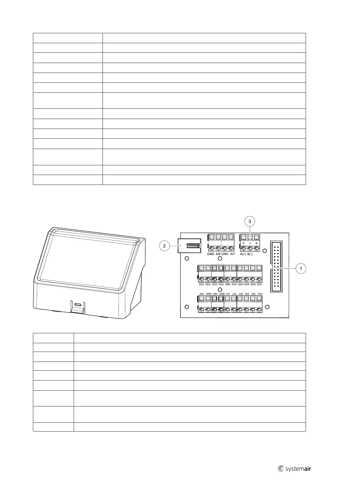
7.2 External connections (Connection board)
External connections to the main circuit board are done via connection board situated outside of the unit.
Fig. 5 External connection box and board
Position Description
1
Connection to the main circuit board
2
Connection for external control panel (HMI) or Internet access module (IAM)
3
Modbus RS485 connection
AI6–7
Freely configurable Analog input. None/Input type selection in HMI.
DO1–4
Freely configurable Digital output. None/Output type selection in HMI.
AO3–5
Freely configurable Analog output. None/Output type selection in HMI. Actuator type 0–10V, 10–
0V, 2–10V, 10–2V.
UI1–5
Freely configurable Universal input. Can be configured to act as Analogue input (0–10V) or as
Digital input (24V). None/Input type selection in HMI (NC or NO polarity).
24V Maximum current 200mA at 24VDC +-10%.
211458 | A002
 Loading...