40
|
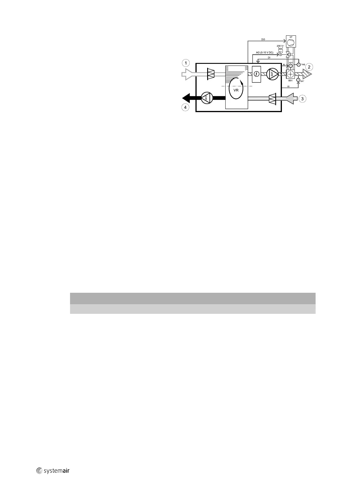
Accessories
• DX — change-over coil
• FPT — frost protection sensor (optional)
• SAT — supply air temperature sensor
• THS — thermostat for feedback from pipe if correct
temperature available for heating/cooling (optional)
• HP — heat pump (or other device for heating and
cooling)
• S — actuator for valve
• 1 — Outdoor air
• 2 — Supply air
• 3 — Extract air
• 4 — Exhaust air
Component/product — Article number:
• RVAZ4 24A Actuator 0-10V (S) — 9862
• Duct sensor -30-70C (SAT) — 211524
• Surface sensor -30-150C (FPT) — 211523
• VSR 300:
ZTV 15-0,4 2-way valve — 9829
ZTV 15-0,6 2-way valve — 6571
ZTR 15-0,4 valve 3-way — 9670
ZTR 15-0,6 valve 3-way — 6573
• VSR 500:
ZTV 15-0,6 2-way valve — 6571
ZTV 15-1,0 2-way valve — 9823
ZTR 15-0,6 valve 3-way — 6573
ZTR 15-1,0 valve 3-way — 6573
Installation and connection
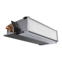
1. Install water heater in the duct. Connect pipes, 2/3–way valve and actuator.
Important
Do NOT use 24V DC power output from the connection board for valve actuator.
2. Connect actuator (S) to any free analog output.
3. Connect the compressor or other device to any free digital output and 24V.
4. The frost protection sensor (FPT) should be strapped on a surface on the return water pipe. Connect FPT sensor to
any free analog input.
5. Internal supply air temperature sensor (SAT, default connection AI2 on the main circuit board) must be replaced by a
duct temperature sensor which can be acquired as an accessory. A duct temperature sensor must be installed in the
duct after water heater: Connect duct temperature sensor in a place of internal supply air temperature sensor (AI2).
6. Thermostat can be used to give feedback if correct water temperature available in the pipes (if heating is demanded
but only cold water available - heating is interlocked). Configure DI as Change-over feedback. This function is
optional.
211458 | A002
 Loading...