Accessories
|
41
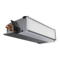
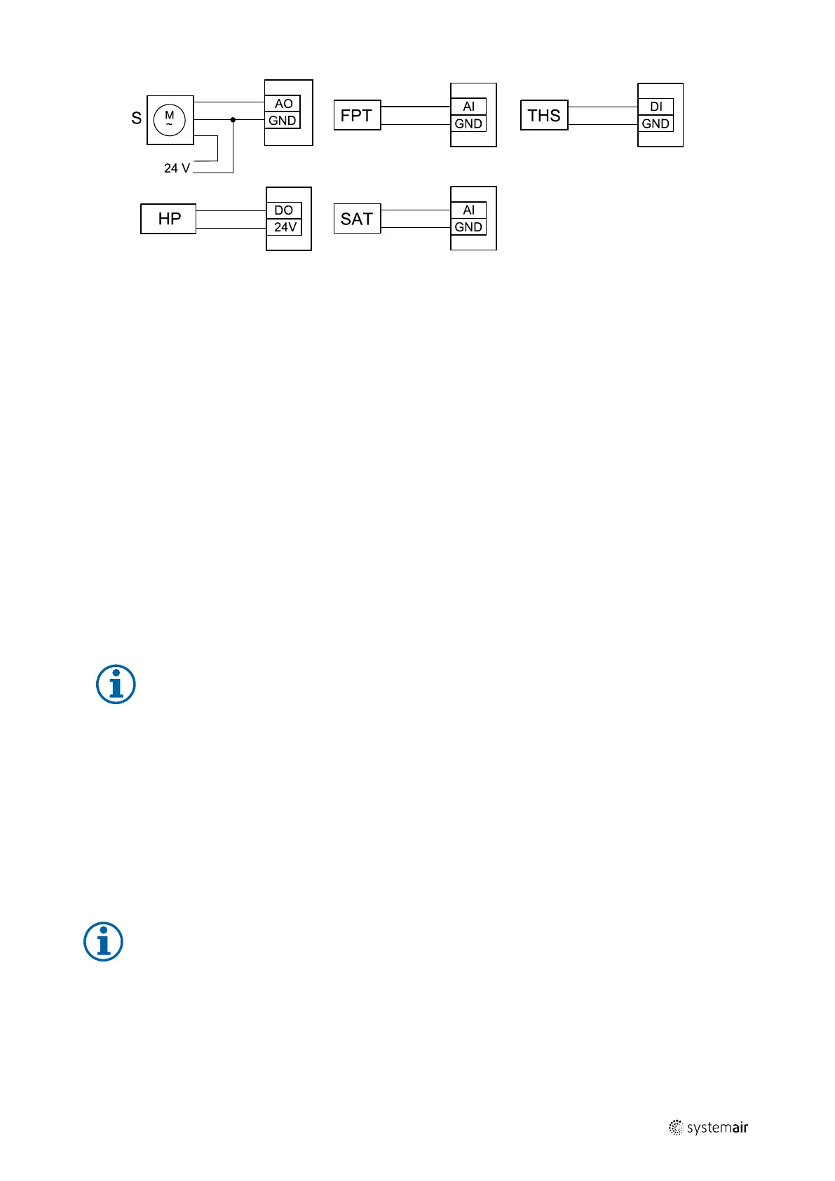
Fig. 15 Change-over heating/cooling connections
Configuration
Before change-over heating/cooling can be activated, it must be configured in the control panel.
1. Go to Service menu
2. Enter password (default 1111)
3. Go to Components menu, select Heater menu and select type as Change-over. Choose actuator voltage type. Do
advanced settings if necessary.
Go to Components menu, select Cooler menu and select type as Change-over. Choose actuator voltage type.
Activate the cooler.
4. Configure connection of the change-over heating/cooling actuator. Go to Service menu. Select Output menu. In
next menu select ANALOG tab. Select the analog output to which the change-over heater/cooler is connected. Exam-
ple if it is connected to AO3 on the connection board, then select ANALOG OUTPUT 3 and select Y1 / Y3 Change-
over from the output type list.
5. Configure frost protection sensor (FPT). Go back to Input menu. Select ANALOG tab. Select the analog input to which
the frost protection sensor is connected. Example if it is connected to AI6 on the connection board, then select ANA-
LOG INPUT 6 and select Frost Protection Temperature Sensor (FPT) from the input type list.
6. Configure thermostat for feedback from pipe. Go to Input menu. Select DIGITAL tab. Select the digital input to
which the thermostat for feedback is connected. Example if it is connected to DI2 on the main board, then select
DIGITAL INPUT 2 and select Change-over feedback from the input type list. Thermostat for feedback can also
be connected to universal input (UI) on the connection board.
7. Since a duct temperature sensor replaces internal supply air temperature sensor, it doesn’t need to be re-configured.
Note:
A duct temperature sensor can be connected to analog inputs 6–7 on the connection board for better
access when the internal supply air temperature sensor is disabled in the control panel. Then temperature
sensor has to be re-configured as universal analog input.
8. Configure cooling activation signal to the compressor or other device. Go to Service menu. Select Output menu. In
next menu select DIGITAL tab. Select the digital output to which the compressor or other device is connected. Ex-
ample if it is connected to DO3 on the connection board, then select DIGITAL OUTPUT 3 and select Activate
Cooling from the output type list.
10.4 Airflow control
10.4.1 VAV/CAV conversion kit
The VAV/CAV conversion kit SAVECair is used for VAV/CAV control of residential units.
Note:
The accessory package contains all needed parts for VAV conversion, however for use with CAV, an IRIS
damper or a similar device with known K factor has to be purchased.
Component/product — Article number:
• VAV/CAV conversion kit SAVECair — 140777
• VSR 300:
SPI-160 C Iris damper — 6753
• VSR 500:
211458 | A002
 Loading...