TB8100 Installation Guide Connection 21
© Tait Electronics Limited February 2007
The DC output from the PMU is 13.65VDC, 27.3VDC, or 54.6VDC
(depending on the model). Although this power output is isolated, the
negative side of the supply is grounded on the system interface board to give
a +V output.
2.2 RF Connections
Important The PA may be damaged if the load is removed or switched
while the PA is transmitting. Refer to “Antenna Load” on
page 6 of the Installation and Operation Manual for more
details.
We recommend that you use dual-screened coaxial cable such as RG223 for
the BNC/TNC connections, and RG214 for the N-type connections.
When the base station is used in simplex mode using a single antenna with
a coaxial changeover relay, the isolation of this relay must be ≥ 40dB.
2.3 System Control Bus
Important In base stations which use a PMU, the PMU must be con-
nected to the system control bus at all times. The I
2
C cur-
rent source is located in the PMU, and if the PMU is dis-
connected, the state of much of the bus will be undefined.
This may cause corrupted data to be present on the bus
when the reciter reads the states of the switches on the con-
trol panel. This in turn may result in random actuations of
microphone PTT, carrier, or speaker key, causing the base
station to transmit or the speaker to be actuated incorrectly.
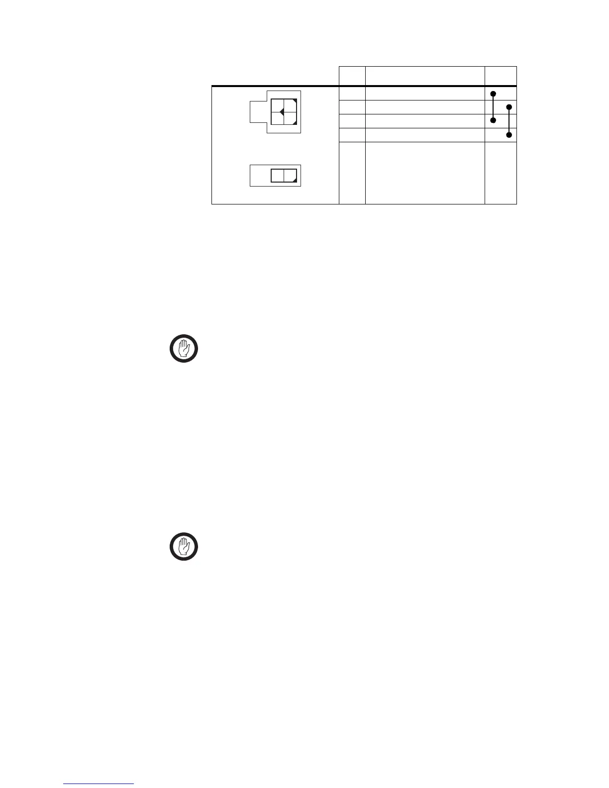
Pin Description Links
1+V input
2 ground
3+V input
4 ground
2-way connector - external view
1
2
3
4
12
4-way connector - external view

 Loading...


