Do you have a question about the Tait TM9300 DMR and is the answer not in the manual?
| Channel Spacing | 12.5 kHz, 25 kHz |
|---|---|
| Operating Temperature | -30°C to +60°C |
| IP Rating | IP54 |
| Frequency Bands | VHF, UHF |
| Bluetooth | Yes |
| Battery Life | N/A (Mobile Radio) |
| Frequency Range | 136-174 MHz |
| Channel Capacity | 2000 channels |
| Operating Modes | Analog |
| GPS | Optional |
| Channels | 2000 |
| Modulation | 4FSK |
Define the purpose and focus of the installation guide.
List related documents for further information.
Detail RF exposure limits and safe antenna placement requirements.
Advise following vehicle manufacturer guidelines for installation.
Refer to the MPT 1362 code for mobile radio installations.
Provide critical safety instructions for securely mounting the radio.
Warn about potential interference with vehicle electronic systems.
Advise caution when drilling to avoid damaging vehicle components.
Highlight special conditions for installing radios in fuel tankers.
Specify safety standards for LPG vehicle installations.
Discuss considerations for heat dissipation in non-standard mounting.
State that radios are designed for negative earth systems only.
Describe U-cradle kits for mounting the main radio unit.
Introduce a security bracket for optional quick-release mounting.
Provide kits for re-installing radios without wiring changes.
Detail kits for installing the control head separately from the radio body.
Kits for extending distances between radio body and control head.
Explain installation options for using two control heads with one radio.
Describe operation and installation of a hand-held remote control.
Kits to extend the distance for hand-held control heads.
Detail using a power supply to operate the mobile radio as a desktop unit.
Cover installation of remote and horn speakers for audio output.
Explain how radio power up/down is controlled via hardware links.
Detail switched and unswitched power for various connectors.
List necessary tools for radio installation procedures.
Outline pre-installation checks of vehicle functions.
Provide instructions for attaching and detaching the control head.
Guide on choosing a safe and convenient location for radio mounting.
Explain conditions under which IP54 rating is maintained.
Detail the process of mounting the U-cradle for the radio.
Cover information on installing an external antenna within RF exposure limits.
Describe how to properly terminate the coaxial antenna cable.
Explain how to connect the radio's power cable to the vehicle's supply.
Detail how to connect an external speaker to the radio.
Cover connections for ignition, emergency switch, and alert devices.
Explain using the ignition signal for radio power control.
Describe connecting an emergency switch to activate emergency mode.
Detail connecting external alert devices via GPIO lines.
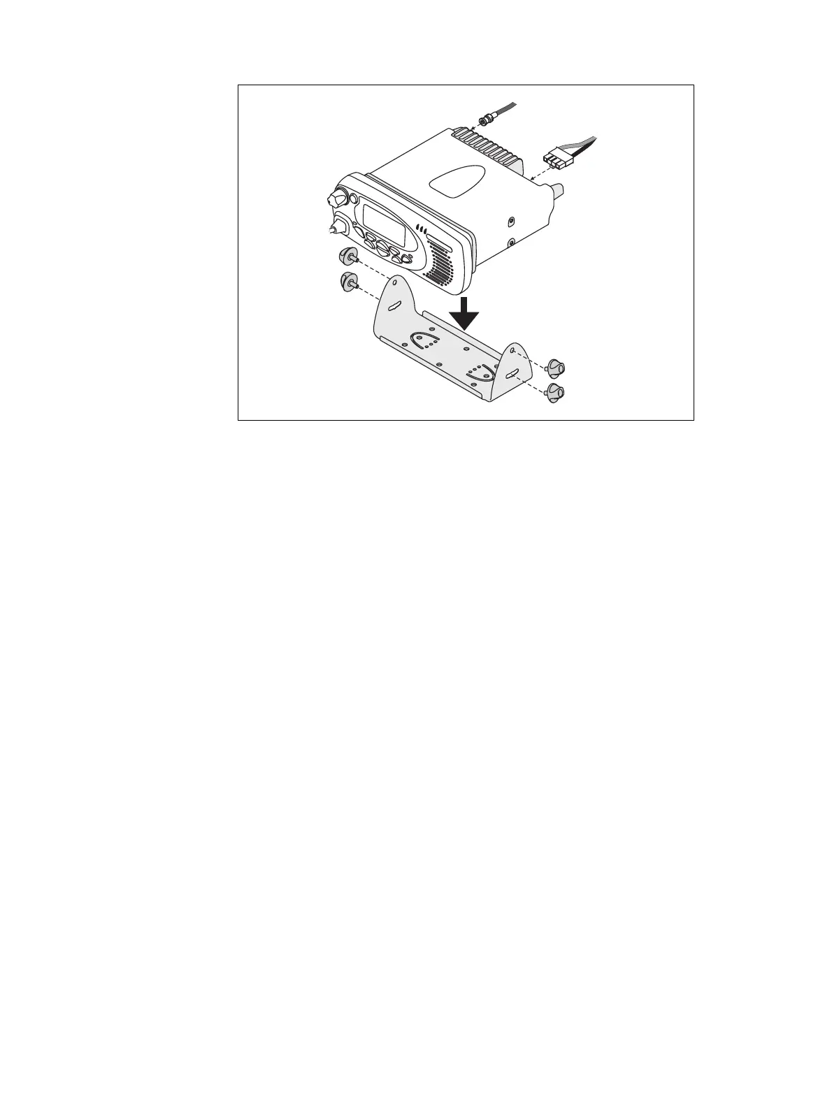
Describes the physical installation of the radio unit into its mounting cradle.
Cover connecting the microphone and installing its clip.
Outline steps to verify the radio installation and performance.
Detail post-installation checks of all vehicle functions.