5-4
USER INTERFACE
Models C709 & C717
User Interface
5
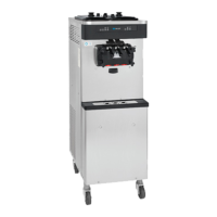
Feed Tube Assembly
The feed tube assembly serves two purposes. One end
of the feed tube is equipped with a mix delivery hole in its
side, and the other end does not.
Figure 5-3
1. Normal Operation
During normal operation, the end of the feed tube
with the mix delivery hole is placed into the mix inlet
hole. Every time the draw handle is raised, new mix
and air from the hopper flow into the freezing
cylinder. This keeps the freezing cylinder properly
loaded and maintains overrun.
Figure 5-4
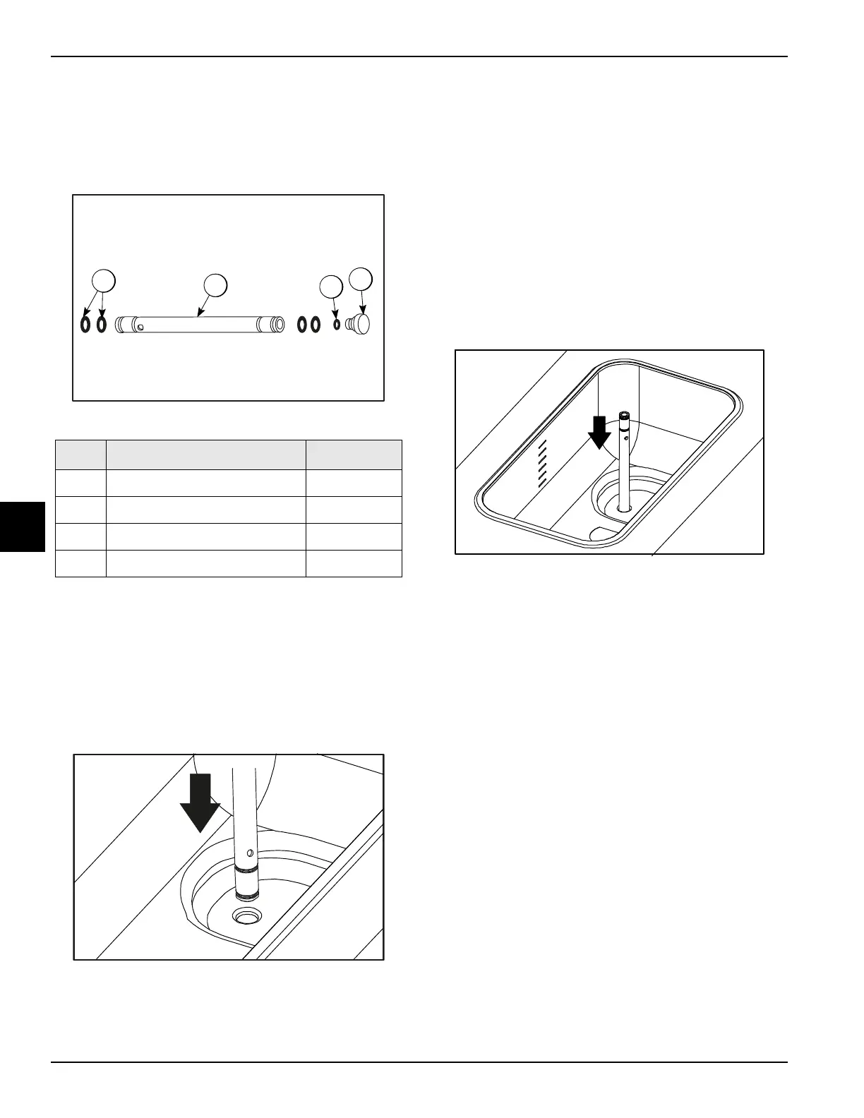
2. Long “No Sale” Periods
During long “no sale” periods, the machine can be
placed into the Standby mode. This maintains
product temperatures below 40°F (4.4°C) in both the
hopper and the freezing cylinder and helps prevent
overbeating and product breakdown.
To place the machine in the Standby mode, press the
Standby key. Using sanitized hands, remove the air
orifice. Lubricate the O-rings located on the end of
the feed tube without the mix delivery hole in its side.
Place that end of the tube into the mix inlet hole. This
will prevent mix from entering the freezing cylinder.
Figure 5-5
Important! When the feed tube is in the standby
position, make sure the level of mix in the hopper is
below the mix delivery hole in the feed tube. Failure to
follow this instruction may result in lower product quality
when normal operation is resumed.
Note: The air orifice is used to meter a certain amount
of air into the freezing cylinder. The air orifice maintains
overrun and allows enough mix to enter the freezing
cylinder after a draw.
Operating Screen Descriptions
The fluorescent display in the center of the control panel
is normally blank during the daily operation of the
machine. The display is activated when the SEL key or
the Manager's Menu is selected. The display screen will
also alert the operator of specific faults detected by the
control.
Note: The displays illustrated in this section are those
seen on Model C709. The Model C717 displays may vary
slightly.
Item Description Part No.
1 Orifice 022465-100
2 O-ring-3/8 OD X .070 W 016137
3 Tube A.-Feed-SS 5/32 Hole X29429-2
4 O-ring-.643 OD X .077 W 018572
 Loading...