14
SECTION 5. ELECTRONIC CONTROL IDENTIFICATION
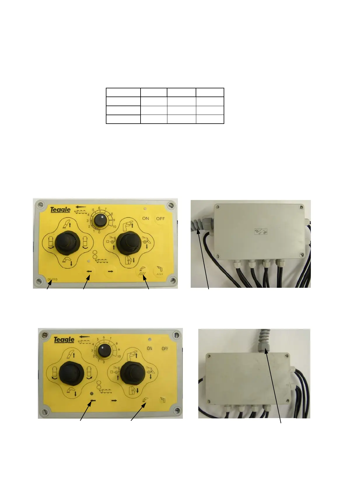
This manual covers the current and previous versions of the electronic control system which can be identified
from figures 5.2 and 5.3 below. It is important to correctly identify the control system before diagnosing problems
or ordering parts as parts of individual systems are not interchangeable. As a guide the current design of controls
were fitted to machines after the serial numbers shown in Table 5.1 below.
Figure 5.2 Current Design - Large Raised Buttons
DL1115 Large Flat Buttons Chop Length Symbols
Control Box
Junction Box
Grey Cable Enters Side
Small Domed Buttons Chute Symbols Only
Figure 5.3 Previous Design - Small Domed Buttons
Grey Cable Enters Top
Control Box
Junction Box
NOTE: All current design control desks have a serial number on the base of the control desk which can be
identified through the aperture of the steel mounting plate. Please quote the serial number when entering into any
correspondence with Teagle Machinery Ltd.
For information on earlier versions of the electronic control system not identifiable from either Figures 5.1 or 5.2
below please contact Teagle Machinery Ltd to obtain the appropriate manual.
Machine Type 808 8080 9090
RH 2520 4290 1770
S/SC
2495 4271 1770
DC/TC
2519 4287 1770
Table 5.1 Last Machines Fitted With Previous Style Controls
 Loading...