4
SECTION 1. INSTALLATION INFORMATION
SAFETY FIRST - READ THE INFORMATION AT THE FRONT OF THIS BOOK
1.1 TRACTOR VALVE CONNECTION
The hydraulic valve block requires an oil supply from a double/single acting valve with an unrestricted return and
must be completely independent of the 3-point linkage. The supply to the valve should be at least 50 litres/min
for correct operation but must not exceed 60 litres/min.
IMPORTANT - Closed Centre Hydraulic System
Where the machine is to be operated on a tractor with closed centre hydraulics, a large volume of oil will be
passing through the valve and motors when the bed chain is in use. This may require the tractor to be fitted with
a free flow “3
rd
Line Return” to return oil from the machine’s hydraulic return hose to the tractor. This will ensure
correct operation of the machine and protect the tractor’s hydraulic system from being damaged. The latest
design of solenoid valve (see section 10.9 page 26 for details) can be modified to permit normal use on tractors
fitted with a closed centre hydraulic system. If in doubt contact your local relevant tractor dealer for advice.
IMPORTANT- Oil must flow through the valve in the correct direction and an identifying tag has been attached to
the pressure line to assist in the correct connection to the tractor spool valve pressure port. Failure to observe
this requirement may result in the valve seals failing.
1.2 CABLE CONTROL INSTALLATION
The control lever mounting bracket should be fitted inside the cab so that the levers are conveniently situated for
the operator. It should be remembered that structural members of the cab must not be drilled or welded and thus
some modification of the mounting bracket may be required. Place the cable control unit in the cab and slot into
the control lever mounting bracket. Route the cables outside the cab clear of any rear linkage components and
PTO shaft.
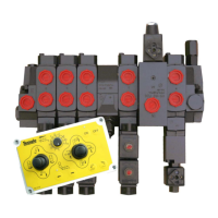
1.3 ELECTRONIC CONTROL INSTALLATION
The electric control box mounting bracket should be fitted inside the cab at either side of the operator so that the
controls are conveniently situated. It is necessary to reverse the control box on its mounting plate if the mounting
bracket is to be fitted to the left of the operator. To reverse the mounting plate carefully remove the lid of the
control box to reveal the heads of the mounting bolts, unbolt the box and refit reversed then replace the lid
making sure the seal is correctly positioned. It should be remembered that structural members of the cab must
not be drilled or welded and thus some modification of the mounting bracket may be required. Place the electric
control unit in the cab and slot into the control box mounting bracket.
Provided with the controls, is a supply cable for direct connection to the tractor battery. The controls have
been designed to be supplied through this cable and WARRANTY SHALL BE INVALIDATED if this
cable is modified. When fitting to the tractor, make sure that the brown cable (positive) is fitted to the positive
terminal of the battery. Failure to connect the wires correctly will cause the in-line 7.5 amp protective fuse to
blow. The fuse will continue to blow until the power supply cables are connected correctly to the battery
terminals. UNDER NO CIRCUMSTANCES SHOULD A FUSE WITH A HIGHER RATING THAN 7.5 AMPS
BE FITTED. When fitting the cable, make sure it is routed away from high temperature and moving engine
components. Avoid sharp edges that would damage the cable, particularly when passing the cable through a
bulkhead. Position the two pin socket in a suitable position within the cab.
Once the control box has been positioned, route the machine cable into the cab making sure it is kept away
from the rear wheels and any pinch points between the PTO shaft and link arms. Where possible, route into
the cab through cable entry points on the tractor, allowing the rear window to be kept closed during use. Plug
the cable connector into the socket on the box and secure by engaging the locking clip.
1.4 ELECTRONIC CONTROL BOX STORAGE
When the machine is not being used, the control box should be stored in a dry location with the connecter
cover closed safely away from the machine to prevent the possibility of water ingress which may damage the
electronics. The plug on the end of the machine cable should be kept clean and stored safe from damage.
1.5 ELECTRONIC CONTROL MAINTENANCE
Teagle Machinery Ltd should be contacted immediately if any problem is found with any aspect of the
electronic controls during the warranty period. The correct course of action shall be advised by a member of
the manufacturer’s Technical Staff. Failure to comply with this request shall INVALIDATE THE
WARRANTY. Before maintaining any part of the electronic controls and wires, disconnect the 12v supply as
failure to do so may result in damage to electronic components.
 Loading...