Do you have a question about the Technics SL-DZ1200PP and is the answer not in the manual?
Test procedure to prevent shock hazards, involving resistance measurement.
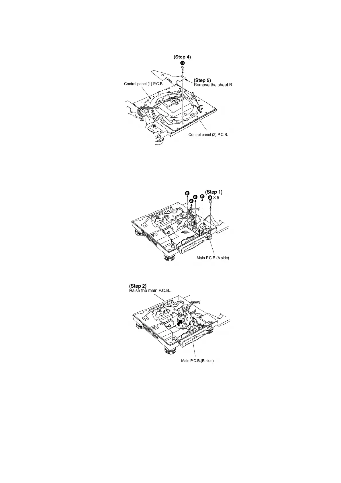
Procedures for checking the control panel PCBs.
Performing ROM/RAM/E2PROM and CD/SD interface diagnostics.
Testing turntable brake performance by measuring stopping time and angle.
Testing turntable speed stability and phase deviation under different tempo settings.
Verifying switch and LED operation by pressing buttons and observing light responses.
Testing LED functionality using LCD display and page switching buttons.
Inspecting SD card save and load operations, checking for OK/NG status.
Initializing the unit to factory preset values, including CUEPAD, LOOP, and AUTOCUE settings.
Testing CD unit by playing first/last titles and automatic reloading.
Procedures for writing programs to SD cards, including file naming and formatting requirements.
Steps to download program files from the TSN SYSTEM via URL.
Process for writing programs to the flash ROM after replacement using an SD card.
Confirming program version and status by pressing SAMPLE PADS and EXECUTE buttons.
Adjusting LCD contrast after IC23 replacement using display angle and function buttons.
Notes and definitions for symbols used in the schematic diagrams.
Table listing test points and corresponding IC pin numbers for the CD servo PCB.
Terminal functions and I/O details for the UI microcomputer IC.
Terminal functions and I/O details for the SC microcomputer IC.
Terminal functions and I/O details for the MD microcomputer IC.
Terminal functions and I/O details for the Servo Amp IC.
Terminal functions and I/O details for the System Control IC.
List of components, accessories, and packaging parts with part numbers and descriptions.
List of CD mechanism parts with part numbers and descriptions.
Covers power supply, jack, main control, panel, motor, CD unit, and LCD unit components.
Explains panel control, CD/SD switching, reverse switch, pitch control, LED, and stroboscope signals.
Details audio output, LCD controls, CD shutter controls, and JTAG/DSP communication.
Communication protocols with CD unit and SDI/F.
Outlines signal paths for Panel, LED, Audio (CD/SD), and Turntable operations.
Troubleshooting steps for power-on issues, including fuse replacement and power supply checks.
Troubleshooting steps for no operation issues, checking LEDs, switches, and microcomputers.
Troubleshooting steps for LCD issues like no display or incorrect characters.
Troubleshooting steps for CD issues like no recognition or failed ejection.
Troubleshooting steps for SD card recognition issues.
Troubleshooting steps for turntable issues like no rotation, irregular rotation, or sound problems.
Troubleshooting steps for audio output problems with LINE OUT and headphone jacks.