12
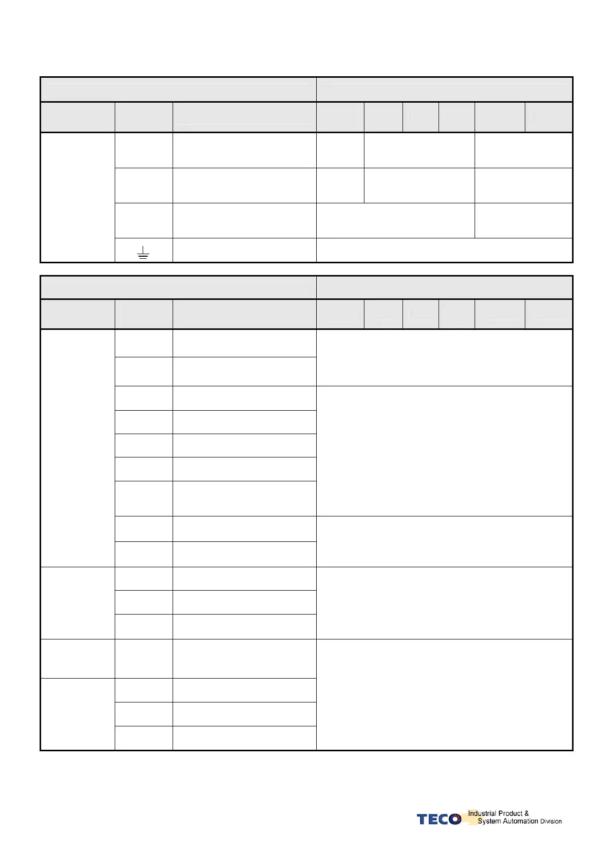
2-1-3 Specifications of Wiring
Connection Terminal Servo Drives and Wire Specifications mm² (AWG)
Connection
Terminal
Mark
(Sign)
Name of Connect Terminal
10 15 20 30 50 75
R、S、T
Main Power Terminal
1.25
(16)
2.0
(14)
3.5
(12)
U、V、W
Motor Terminal
1.25
(16)
2.0
(14)
3.5
(12)
P、Pc
xternal regeneration resistance
terminal
1.25
(16)
2.0
(14)
Terminal
Ground
2.0
(14)
Connection Terminal Servo Drives and Wire Specifications
Connection
Terminal
Position
Number
Position Name
10 15 20 30 50 75
12,25
peed Command / Limit ; Torque
Command / Limit (SIC/ TIC)
13 Analog Signal Ground (AG)
0.2mm ² or 0.3mm ² ->Twisted-pair-cable connecting to
the Analog Grounding wire (including shield cable)
1~3
14~16
Digital Input (DI)
18~20 Digital Output (DO)
8 +24V Power Supply (IP24)
17 Digital Input Common (DICOM)
24 +24V Ground (IG24)
0.2mm ² or 0.3mm ²-> Twisted-pair-cable connecting to
the I/O Grounding wire
(including shield cable)
4~7
Position Command Input
(Pulse、Sign)
CN1
Joint Control
Signal
9~11
21~23
Encoder Signal Output
P
、/PA、PB、/PB、PZ、
PZ)
0.2mm ² or 0.3mm ²-> Twisted-pair-cable
(including shield cable)
5 +5V Power Supply (+5E)
4 +5V Ground (GND)
CN2
Joint of motor
encoder
1~3
7~9
Encoder Phase Input
(A、/A、B、/B、Z、/Z)
0.2mm ² or 0.3mm ²-> Twisted-pair-cable
(including shield cable)
CN3
Communication
connector
5,7
Communication connector
(RS-485)
1,4
Communication connector
(RS-232)
3 Communication Ground
CN4
Communication
connector
5,7
Communication connector
(RS-485)
0.2mm ² or 0.3mm ²-> Twisted-pair-cable
(including shield cable)
P. S .: 1. Please pay attention to the NFB and the capacity of noise filter when using multi-Drives.
2. CN1 ->25 Pins (D-SUB)
3. CN2 -> 9 Pins (D-SUB)
4. CN3/CN4-> 8 Pins Mini-Din type
 Loading...