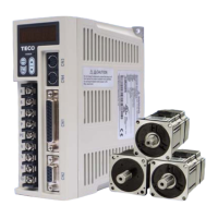
III
Table of Contents
CHAPTER 1 CHECKING AND INSTALLING................................................................................ 1
1-1
C
HECKING
P
RODUCTS
............................................................................................................. 1
1-1-1 Confirming with Servo Drives ........................................................................................ 1
1-1-2 Confirming with Servo Motors........................................................................................ 2
1-1-3 Servo motor Model Code display................................................................................... 3
1-2
A
B
RIEF
I
NTRODUCTION OF
O
PERATION FOR
D
RIVES
................................................................. 5
1-3
C
ONDITIONS FOR
I
NSTALLATION OF
D
RIVES
.............................................................................. 6
1-3-1 Environmental Conditions.............................................................................................. 6
1-3-2 Direction and Distance .................................................................................................. 7
1-4
C
ONDITIONS FOR
I
NSTALLATION OF
S
ERVO
M
OTORS
................................................................. 8
1-4-1 Environmental Conditions.............................................................................................. 8
1-4-2 Method of Installation .................................................................................................... 8
1-4-3 Notice for install motor................................................................................................... 9
CHAPTER 2 WIRING .................................................................................................................. 10
2-1
B
ASIC
W
IRING FOR
S
ERVO
S
YSTEM
....................................................................................... 10
2-1-1 Wiring for Main Circuit and Peripheral Devices ........................................................... 10
2-1-2 Wiring for Servo Drives.................................................................................................11
2-1-3 Specifications of Wiring ............................................................................................... 12
2-1-4 Motor Terminal Layout................................................................................................. 13
2-1-5 Typical Wiring for Motor and Main Circuit .................................................................... 15
2-1-6 TB Terminal ................................................................................................................. 16
2-1-7 Wiring for Mechanical Brake........................................................................................ 16
2-2
I/O
T
ERMINAL
....................................................................................................................... 17
2-2-1 Output Signals from the Servo pack............................................................................ 18
2-2-2 Encoder Connector (CN2) Terminal Layout................................................................. 19
2-2-3 Communication Connector (CN3/CN4) Terminal Layout ............................................. 20
2-3
T
YPICAL
C
IRCUIT
W
IRING
E
XAMPLES
..................................................................................... 21
2-3-1 Position Control Mode (Pe Mode) (Line Driver)........................................................... 21
2-3-2 Position Control Mode (Pe Mode) (Open Collector) .................................................... 22
2-3-3 Position Control Mode (Pe Mode) (Pi Mode).............................................................. 23
2-3-4 Speed Control Mode (S Mode).................................................................................... 24
2-3-5 Torque Control Mode (T Mode)................................................................................... 25
CHAPTER 3 PANEL OPERATOR / DIGITAL OPERATOR......................................................... 26
3-1
P
ANEL
O
PERATOR ON THE
D
RIVES
......................................................................................... 26
3-2
T
RIAL
O
PERATION
................................................................................................................. 27
CHAPTER 4 PARAMETER ......................................................................................................... 28
4-1
E
XPLANATION OF
P
ARAMETER GROUPS
.................................................................................. 28
4-2
P
ARAMETER
D
ISPLAY
T
ABLE
.................................................................................................. 28

 Loading...