Operation
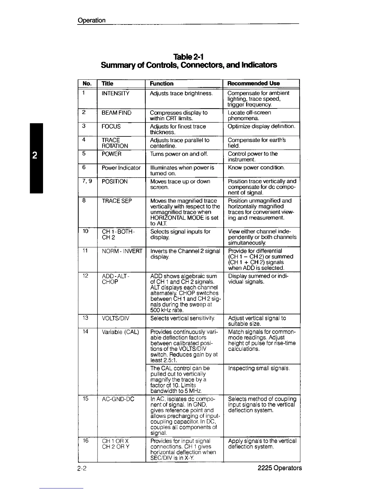
Table 2-1
Summary of Controls, Connectors, and Indicators
No. Title Function
Recommended Use
1
INTENSITY Adjusts trace brightness.
Compensate for ambient
lighting, trace speed,
trigger frequency.
2
BEAM FIND Compresses display to
within CRT limits.
Locate off-screen
phenomena.
3
FOCUS
Adjusts for finest trace
thickness.
Optimize display definition.
4
TRACE
ROTATION
Adjusts trace parallel to
centerline.
Compensate for earth’s
field.
5
POWER
Turns power on and off.
Control power to the
instrument.
6
Power Indicator Illuminates when power is
turned on.
Know power condition.
7, 9
POSITION Moves trace up or down
screen.
Position trace vertically and
compensate for dc compo
nent of signal.
8
TRACE SEP
Moves the magnified trace
vertically with respect to the
unmagnified trace when
HORIZONTAL MODE is set
to ALT
Position unmagnified and
horizontally magnified
traces for convenient view
ing and measurement.
10
CHI - BOTH -
CH 2
Selects signal inputs for
display.
View either channel inde
pendently or both channels
simultaneously.
11
NORM - INVERT Inverts the Channel 2 signal
display.
Provide for differential
(CH 1 - CH 2) or summed
(CH 1 + CH 2) signals
when ADD is selected.
12
ADD-ALT -
CHOP
ADD shows algebraic sum
of CH 1 and CH 2 signals.
ALT displays each channel
alternately. CHOP switches
between CH 1 and CH 2 sig
nals during the sweep at
500 kHz rate.
Display summed or indi
vidual signals.
13
VOLTS/DIV Selects vertical sensitivity. Adjust vertical signal to
suitable size.
14
Variable (CAL)
Provides continuously vari
able deflection factors
between calibrated posi
tions of the VOLTS/DIV
switch. Reduces gain by at
least 2.5:1.
Match signals for common
mode readings. Adjust
height of pulse for rise-time
calculations.
The CAL control can be
pulled out to vertically
magnify the trace by a
factor of 10. Limits
bandwidth to 5 MHz.
Inspecting small signals.
15
AC-GND-DC
In AC, isolates dc compo
nent of signal. In GND,
gives reference point and
allows precharging of input
coupling capacitor. In DC,
couples all components of
signal.
Selects method of coupling
input signals to the vertical
deflection system.
16
CH 1 OR X
CH 2 OR Y
Provides for input signal
connections. CH 1 gives
horizontal deflection when
SEC/DIV is in X-Y.
Apply signals to the vertical
deflection system.
2-2
2225 Operators
 Loading...


