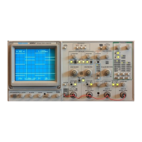
Operator Checks and Adjustments
2. Connect the probe tips to the PROBE ADJUST connector and the probe
ground leads to scope ground.
3. Set:
VERTICAL MODE CH 1
Horizontal MODE A
4. Press AUTO SETUP button.
5. Set the CH 1 VOLTS/DIV setting to 0.1 V (10 mV with probe discon
nected) and vertically center the PROBE ADJUST square-wave signal.
6. Check the square-wave signal for overshoot and rolloff (see Figure
4-1). If necessary, use the special adjustment tool supplied in the probe
accessory package to adjust the low-frequency compensation for a
square front corner on the square wave displayed.
7. Press the CH 2 VERTICAL MODE button to turn CH 2 on in the display,
and press the CH 1 Mode button to remove the CH 1 trace from the
display.
8. Set the CH 2 VOLTS/DIV setting to 0.1 V (10 mV with probe discon
nected) and vertically center the PROBE ADJUST square-wave signal.
9. Repeat Step 6 for the second probe on the CH 2 BNC input connector.
NOTE
Refer to the instruction manual supplied with the probe for
more detailed information about the probes and adjustment
procedure.
4-4
2245A Operators

