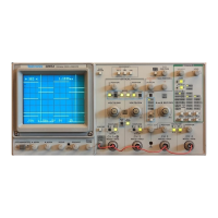
Do you have a question about the Tektronix 2245A and is the answer not in the manual?
| Type | Analog Oscilloscope |
|---|---|
| Bandwidth | 100 MHz |
| Channels | 4 |
| Vertical Sensitivity | 2 mV/div to 5 V/div |
| Rise Time | 3.5 ns |
| Display | CRT |
| Power Supply | 48 to 440 Hz |
| Weight | 20 lbs |
| Max Sample Rate | N/A (Analog Oscilloscope) |
| Input Impedance | 1 MΩ ±2%, ~20 pF |
Overview of the 2245A oscilloscope's features including microprocessor control, measurement systems, and setup capabilities.
Safety precautions for power source, grounding, and general instrument usage.
Description of CRT display, power switch, intensity, focus, and scale illumination controls.
Details on CH 1/CH 2 position, mode selection (CHOP/ALT), and input coupling.
Fundamental operating information and techniques for making measurements with the oscilloscope.
Procedure to activate voltage measurement cursors and display voltage differences.
Performing self-characterization of vertical channels and horizontal timing for calibration.
Using the AUTO SETUP function to automatically configure controls for a usable signal display.
Accurately measuring voltage on displayed signals using positionable horizontal cursors.
Guideline for making voltage difference measurements using positionable voltage cursors.
Guideline for making time difference measurements using the TIME cursors.
Verifying the accuracy of time and frequency measurements using SEC and 1/SEC cursors.
Testing the AUTO SETUP function to ensure it produces a stable display of the probe adjust waveform.
Table detailing the front-panel control actions performed by the AUTO-SETUP function.