Checks and Adjustments
Probe Compensation
Accurate measurements require accurate probe compensation. To ensure
optimum measurement accuracy, check probe compensation any time a probe is
attached to the instrument or any other time you are not certain of correct
compensation. Because of minor differences between channels, CH 1 and CH 2
probes should be compensated on their respective channels. CH 3 and CH 4
probes should be compensated on CH 1 or CH 2. Check and adjust probe low-
frequency compensation as follows:
1.
Obtain a display as described in "Initial Setup."
2.
Set the SEC/DIV control to
1
ms and 20 MHz BW LIMIT
on.
If the probe to
be compensated is connected to CH 2, enable the Channel 2 display. Set
the appropriate VOLTS/DIV control to 100 mV.
3. Connect the probe to the CALIBRATOR output.
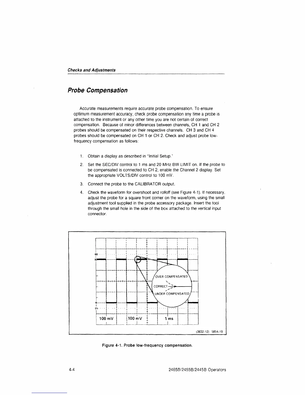
4.
Check the waveform for overshoot and rolloff (see Figure 4-1). If necessary,
adjust the probe for a square front corner on the waveform, using the small
adjustment tool supplied in the probe accessory package. Insert the tool
through the small hole in the side of the box attached to the vertical input
connector.
100 mV
(3832-12) 5854-19
Figure
4-1.
Probe low-frequency compensation.
4-4
2465B/2455B/2445B Operators
 Loading...


