42.
SOURCE-Determines
the source
of
the trigger
signal coupled
to
the
input
of
the
trigger
circuit.
NORM:
Trigger
source is displayed signal(s). It does
not
indicate time relationship between CH 1 and CH 2
signals. However, stable
triggering
of
non-time-related
signals usually can be obtained
by
setting VERT MODE to
ALT, SOURCE
to
NORM and
COUPLING
to
LF REJ.
Carefully
adjust LEVEL
for
a stable display.
CH
1: A sample
of
the signal available in Channel 1
is
used as a
trigger
signal. CH 2 signal
is
unstable if it
is
not
time-related.
CH
2:
A sample
of
the signal available in Channel 2
is
used as a
trigger
signal. CH 1 signal
is
unstable if it
is
not
time-related.
LINE (A
Trigger
circuit
only): A sample
of
the power-
line
frequency
is used
as
a
trigger
signal. It is useful when
the
input
signal is time-related
(multiple
or
submultiple) to
the line frequency
or
when it
is
desirable to provide a
stable display
of
a
line-frequency
component
in a complex
waveform.
EXT: Signals connected
to
the External
Trigger
Input
connectors
are used
for
triggering. External signals must
be time-related
to
the displayed signal
for
a stable display.
It is useful when the internal signal
is
too
small
or
contains
undesired signals that
could
cause unstable triggering. It
is useful when operating in
CHOP
mode.
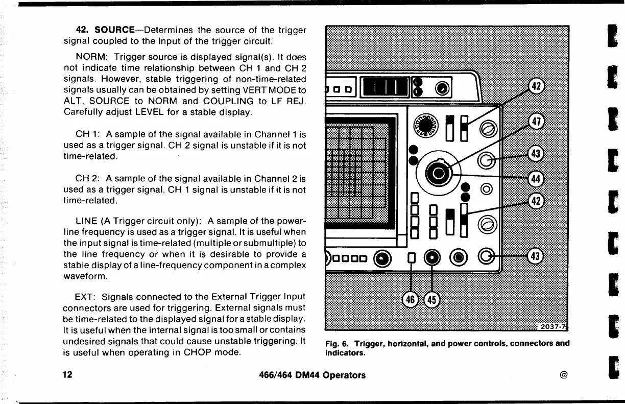
Fig.
6.
Trigger,
horizontal, and
power
controls,
connectors
and
indicators.
12
466/464 DM44 Operators
@
I
I
I
I
I
I
 Loading...


