J
J
J
J
J
l
J
J
J
k
L.
-
OPERATOR'S
ADJUSTMENTS
AND CHECKS
To
verify
measurement accuracy, perform the
follow-
ing
checks
and adjustments before
making
a measure-
ment. See the
Calibration
section
of
the Service manual
for
calibration
information.
Trace Rotation Adjustment
Normally
not required. Obtain a
Normal
Sweep Display
using
only
steps 1
through
3.
Set the CH 1
input
Coupling
switch
to
GND
to display a
free-running
trace with no
vertical deflection. Adjust
the
TRACE
ROTATION
(screw-
driver
adjustment
located below the
crt
graticule)
to
align
the trace
with
the center horizontal
graticule
line.
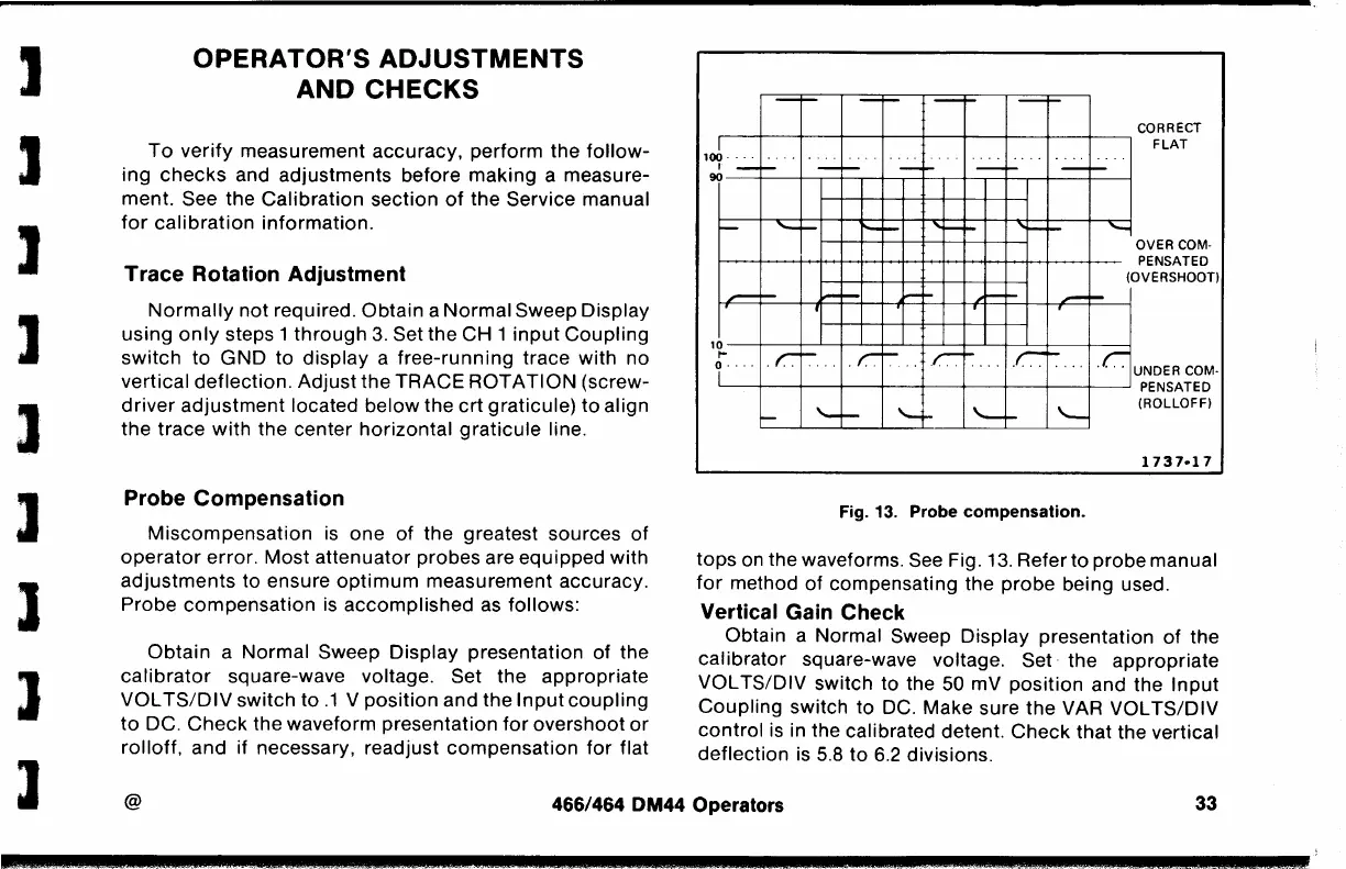
Probe Compensation
Miscompensation
is
one
of
the greatest sources of
operator
error. Most attenuator probes are equipped
with
adjustments
to ensure
optimum
measurement accuracy.
Probe
compensation
is
accomplished
as
follows:
Obtain
a Normal Sweep Display presentation of the
calibrator
square-wave voltage. Set the appropriate
VOL
TS/DIV
switch to
.1
V
position
and the
Input
coupling
to
DC.
Check
the waveform presentation
for
overshoot
or
rolloff,
and if necessary, readjust
compensation
for
flat
--
CORRECT
I~-+--+--+-~--+--+--+---+--+----,
FLAT
100...
.
..
I
--
~~-+---+--~,___,.-+-~-+-..,--+-.--+--.--+--+-~
--
--
_.,_
'--
--
,_
....
• I
'
,
__
---
OVER COM-
PENSATED
(OVERSHOOT)
10~...j_-+..-L....j.___J_-+---L--+--L-........,-+---'--+---+-~
r ·
r.~
· ·
r.-
.C'~
· ·
.c-.
· · · . C UNDER COM-
IL__--+--+--+-----1--+---+--+---t--t-___J
PENSATED
'--
'--
(ROLLOFF)
1737·17
Fig. 13. Probe
compensation.
tops
on
the waveforms.
See
Fig.
13.
Refer to probe manual
for
method
of
compensating the probe being used.
Vertical Gain Check
Obtain a Normal Sweep Display presentation
of
the
calibrator square-wave voltage. Set· the appropriate
VOL TS/DIV switch to the 50 mV
position
and the
Input
Coupling
switch to DC. Make sure
the
VAR VOL
TS/DIV
control
is
in the calibrated detent.
Check
that the vertical
deflection
is
5.8
to
6.2 divisions.
@
466/464 DM44 Operators
33
--¥
...
 Loading...


