Do you have a question about the Tektronix 760A and is the answer not in the manual?
Overview of the instrument, its features, and technical specifications.
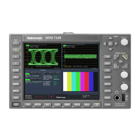
General description of the 760A Stereo Audio Monitor and its purpose.
Highlights the key features of the Stereo Audio Monitor.
Details the CRT display's function for monitoring stereo separation and phase.
Describes the 100-segment LED bar graph for signal level indication.
Guide to operating the 760A Stereo Audio Monitor.
Familiarizes the user with the instrument's controls, connectors, and displays.
Describes the functions of all front-panel controls.
Details the audio input connectors on the rear panel.
Explains the CRT display's visual feedback for amplitude and phasing.
Describes the 'Sound Stage' and alternate XY graticule orientations.
Provides instructions for installing the instrument.
Instructions for unpacking the instrument and saving packaging.
Covers power source and mains voltage requirements.
Specifies the instrument's intended power source.
Covers preventive maintenance, troubleshooting, and corrective actions.
Discusses preventive maintenance, troubleshooting, and corrective maintenance.
Details cleaning, visual inspection, and performance checks.
Instructions for cleaning the exterior and interior of the instrument.
Information for repair procedures.
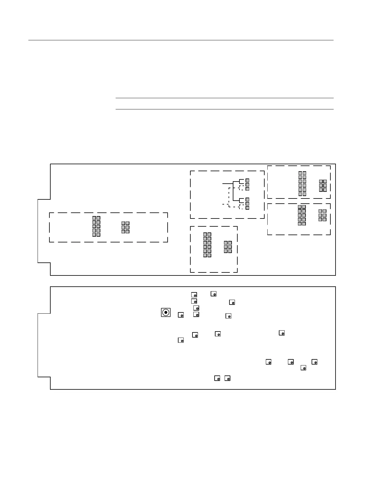
Explains how to use foldout pages and diagrams for troubleshooting.
Provides information for isolating problems, especially with the DAC.
Describes ROM information for troubleshooting DAC issues.
Guides for troubleshooting power supply issues.
Procedure for checking and troubleshooting the low voltage supply.
Instructions for disassembling and reassembling mechanical parts.
Step-by-step guide for removing the instrument's bezel.
Procedures to verify and restore instrument specifications.
Describes the two procedures: Performance Check and Adjustment.
Lists minimum test equipment needed for procedures.
Guide to verifying warranted specifications of the 760A.
Step-by-step process for initial instrument alignment.
Detailed steps for calibrating the instrument.
Initial setup steps before calibration adjustments.
Explains the operational theory and relationships between functional blocks.
Provides a thorough understanding of the 760A/760D/760N operational theory.
Shows relationships between major functional blocks of circuitry.
Describes circuitry in detail, relating blocks to schematic diagrams.
Explains the function of the input amplifiers.
Documents available instrument options.
Describes instrument options available for the 760-Series.
Details the available CRT phosphor options.
Contains a list of electrical components for replacement.
Information on how to order replacement parts from Tektronix.
Explains the structure and features of the electrical parts list.
Contains illustrations of diagrams and circuit boards.
Explains graphic symbols and logic symbology used in diagrams.
Defines units for capacitors and resistors shown on diagrams.
Lists replaceable mechanical components for the instrument.
Information on how to order replacement mechanical parts.
Explains the structure of the mechanical parts list.
Overview of the manual's structure and content.
Includes sections relevant to instrument operators.
Includes sections relevant to service technicians.
General description and specifications of the instrument.
Familiarizes users with instrument operation and controls.
Covers electrical and mechanical installation procedures.
Provides information on maintenance and troubleshooting.
Details performance checks and calibration steps.
Documents available instrument options.
Lists electrical components available for replacement.
Contains servicing illustrations, diagrams, and waveforms.
Lists replaceable mechanical parts and ordering information.
Precautions to prevent fire or personal injury during use.
Defines warning symbols and terms used in the manual.
Safety warning against performing service alone.
Instruction to disconnect power before servicing.
Safety precautions for servicing the CRT.
Information regarding X-radiation safety.