Installation and Removal Instructions
The
DM
501A
is calibrated and ready to use
when
received. It operates in one compartment
of
a TM
500-
Series
power module. Refer
to
the power
module
instruc-
tion
manual for
line
voltage requirements
and
power
module operation.
CAUTION^
Turn the power
module
off before
inserting or
removing the
DM 501 A;
otherwise,
arcing may occur
at
the rear interface connectors. Arcing
reduces the
connectors useful life
and
damage
may be done to
the plug-in circuitry.
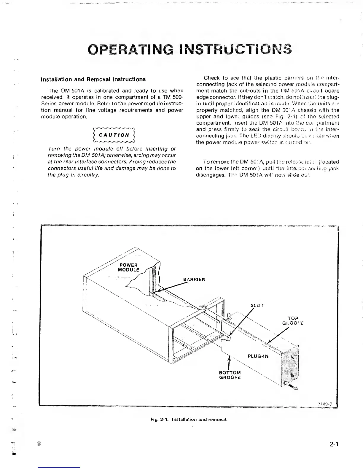
Check to
see that tlie plastic
barriers
on
tihe inter-
connecting jack of the selected power
moduie compart-
ment
match
the cut-outs in the
DM
501A ci.cuit board
edge connector,
if they don't match, do not
insc; :
the plug-
in until proper
identification
is rnr.de.
Vv'hen
tire
units
nie
properly
matched, align
the DM
501A chassis with
ttie
upper and
lowe;
guides
(see
Fig. 2-1)
of
tno
selected
compartment. Insert the DM
501 A
mto tire con p.'irtment
and press firmly to seat
the
circuit
born.,
in
tiie
inter-
connecting jack. The LED'
display
shouio
he
\'i : ibio
wuen
the
power
mocir.e power switch
is
iurriC'd
oir
To remove the DM 501 A, puli the roleasc lai
n
.
(located
on the lower left
come
)
until ttie
inte. con.'ic-i
iii,g
jack
disengages.
The
DM
501
A
will now slide oub
Fig.
2-1.
Installation
and removal.

 Loading...


