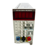
Operating Instructions—
DM 501
A
CONTROLS
AND
CONNECTORS
4-
i/2
digit LED
readout with
decimal point
positioned by the selected
range push
button
switch.
Range selector
push button switches for volts,
ohms, current or decibel
measurement.
Fror;t-panel
mA
input used in
conjunction with the
LOW input
for
current
measurement.
Tempe''nture
probe input connector.
Chassis ground binding
post.
A
Front-panel inputs
for
volts, ohms
and
decibel measurement.
cr peraturo Input ‘unction
rnish button.
INPUT
APush
button selects
either
rear interface
inputs
or
front-panel
inputs for measurement
mA
©
Ac current
function push button.
Dc current
function push button.
Pubi'i button selects
Ml or LO as probe
tip voltage
tor
measuring ohms.
O.hins function
push button.
VOLTS
A
Decibel
function pus.h button (used in con-
junction with the AC
volts push button).
Ac volts
function
push
button.
Dc
volts function
push
button.
Release
latch. Pull
to remove plug-in.
Refer
to
General
Operating
Information.
Genera! Operating Information
With the DM 501A properly installed
in
the power
module and the power switch on, allow thirty minutes
warm-up time for operation
to
specified accuracy. Select
the desired measurement function and range. When the
value
of the
quantity
measured is unknown, select the
highest range first. Decrease the range setting until the
display reads between 10% and 100% of the full-scale
reading. This
particular
range will give maximum resolu-
tion. When an
input
signal causes the display to read
greater than
19090,
an overrange blinking display occurs.
This blinking ind-cates the input
is
greater than the
full-
scale reading on the particular
range selected.
The 1000
Vdc
and 500 Vac range will
not cause a
blinking display when the input signal exceeds the
maximum allowable input
on
this range.
S
CAUTION
(
)
i
Instrument damage may occur
if
maximum
input
potential is
exceeded.
Input Connections
Four input connectors
provide front-panel measure-
ment connections. The
VOLTS/Q
and LOW
input connec-
tors
are
used
for dc voltage, ac voltage, dBV,
dBm and ac
and dc
resistance measurements. The mA and
LOW input
connectors are
lised
for
ac or dc current measurements.
The input EXTANT push button selectsfront-panel or
rear
interface input.
Rear interface
pins 28A (LO)
and
28B
(HI)
are used for
rear interface voltage, dB and
resistance
measurements.
The TEMP input connector
is used for
temperature
measurements.
CAUTION
^
^
^ .y
To avoid
erpitpment damage, do not apply a
voltage
exceeding
200
V
peak
between pins
28A
and 28B
of
the rear
intorl.ice connector.
Normal
measurement conditions are
with
the LOW
connector
referenced fo
the device-under-test
common.
A
connection
between the
LOW input
connector
and the
ground
terminal may be
made to reference
the
input
to
the
DM 501A
chassis ground. Use
caution as
the LOW
connector is
connected to
earth ground
through
the
power
module ttiree-wire
power cord.
2-2

 Loading...


