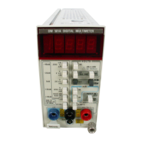
Calibration Procedure-—
DM 501A
Performance Check
Procedure
6. Chock Ohms
Accuracy
a C'jnneo.t
a lesistance
standard to the
VOLTS/Q
and
L
rrw
f
(innectors
1
.
1
. I’/oss
ihe
KO
fiji'otion
push
button and the ap-
l'irr’pr!,!t(.^ I
i|
ur 1 O
push button
as inriicated
in
Table
4-6.
/,
the
range
push button
and set the
resistance
stdrr.laMJ
as listed
in Table
4-6
iT
Chock that
tfie DM 5G1A
display
reads within the
(lisr.'b
y
limits
for
the ambient
temperature
as
listed in
1
a!
he
a
('<
all connoctions.
7.
C'lecl'.
Dc Current
Accuracy
a,
'
''
ssiuct thu
dc
current
source to
the
mA
and
LOW
nMnoi
tui':; t!-,ts'ii;ih
appropriate
cables
and connectors
w'.hh t.he
I'losi’ivo
source to the rnA
connector
1.1
fVess the
luA
t'C
'u.nct'ori piisti
trutton
c. Press the rancje
push button arid
set ttie current
souu
i-;
as listed
in Table
4-7.
d. Cheek llidt
tile DM
50
1 A
display
readout
is within
the display
limits
for the
anibient temperature
as
shown in
Table
4-7
0 I iL-ni.jve the do
cuiront soiirceand
all connections
8 Ciuock
Ac Current Accuracy
, 1
.
Kinimt
Ihv;
precision ac current
souce to the rnA
and
I CiVJ
connortors throupli
appropriate cables and
r ainuotors
b
i’rnss
the mA
AC
function pustr
button.
o I os.,
the rancje push
button and
set the current
souM.t.'
as
listed
m
Table
4 8
d.
Check—
that
ttio DM
50IA display
reads within
the
disp!.iy
I’l.nils
fn.r
Pie ambient temperature
as
listed in
Tab'e
d.o
e. Remove
the AC current
source
and all
connections
9.
Check Temperature
Accuracy
a. Connect the
temperature
probe to
the
TEMP
con-
nector
located
r-ri
Pie
front panel.
b.
Press the
IT.MP“C
push button.
c, Sol
the terii'ierature bath for
the first
temperatures
shown in the Tr.irni
-erature column in Table
4-9.
d
Insert
the ra-
ibe
in
the
bath and allow
the probe to
stabilize .it
the
S'-U cted
temperature.
e.
Check—
that
the display limits
are as listed in Table
4-9.
f. Re[ieat p.drl ;
c, d, and
e
for the
subsequent
lemi'eralures lltded in Table
4-9.
g
Tfiis cotn|iic-!es
the
front
panel performance
check.
Rear
Interface Accuracy Checks
T
o
verify the .ic-
uracy of the dc voltage, ac
voltage and
resistance modus
via
the
DM
501A roar interface, follow
the steps
outliricd
in the Performance Chock Procedure
for
the
front panel
input connectors, but apply the
voltages
and resistances
t(,
rear interface pins
28B
(HI) and 28A
(LO).
Access
to
th.i
rear interface pins
is
most easily made
using a IM 500
ss-ries,
Option
2
power module.
Press the
fri..*nt
panel
EXT-INT
push button
to
select
rear interface infu.l
and
use
Table 4-10, Table
4-
1
1,
Table
4-12, Table
4-1.!
or
Table
4-14
for the
appropriale input
voltages, froqu'
ncies,
and
display limits.
NOTE
The oiitpul
c<ihio fixture from the calibrating sources
to the rear m’et'.ace pins may have
to
be
modified
to
accommoda!
'
.'cctiracy checks via the rear
inter-
face.

 Loading...


