AvijuSwiiehi
Kioceaurc
ADJUSTMENT PROCEDURE
Introduction
Use
this Adjustment Procedure to restore
the
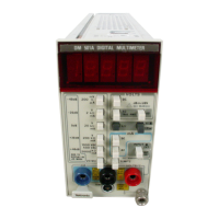
DM 501
A
to
original performance requirements.
This Adjustment
Procedure need not be performed unless the
instrument
fails to meet the Performance Requirements of the
electrical characteristics
listed in
the Specification sec-
tion,
or
if
the Performance Check procedure cannot
be
completed satisfactorily. If the instrument has undergone
repairs, the Adjustment
Procedure
is recommended.
Satisfactory completion
of
all
adjustment
steps
in this
procedure
ensures that
the
instrument will
meet the
Performance
Requirements.
Test Equipment Required
The
test
equipment
(or equivalent) listed in Table
4-1
is
required for adjustment of the DM 501A. Specifications
given
for the test equipment are the minimum necessary
for accurate adjustment.
All
test equipment
is
assumed
to
be
correctly calibrated
and operating
within
spec-
ifications.
If
other test
equipment is
substituted, calibration setup
may need
to
be
altered
to meet the requirements
of
the
equipment
used.
Preparation
Access
to the
internal
adjustments is
achieved most
easily
when the DM 501A
is connected
to
the power
module with a flexible
plug-in
extender.
Remove the
left
side
cover of the
DM
501 A to
access the adjustments on
the main and
attenuator
boards.
The electrical shield must
be
removed to make temperature
adjustments.
See
Fig.
8-3
in
the Diagram section at
the rear of this manual.
Remove the
power module cabinet
to make ad-
justments
to
the DM
501 A inside
the
power
module.
Install
the
DM
501A
in
the
right
side compartment
of the
power
module with
its unused compartments
on the
left side.
Make
adjustments at an ambient
temperature between
2rC and
25'’C
(70°F
and 77“F).
1.
Check
Power Supplies
a.
Set
the test voltmeter to the
20 V range.
b.
Connect one lead
of the voltmeter to
the
1
15
V point
located
on the Main board,
and the ottrer lead to the
LOW
test point.
c.
Check
—fora
I
15
V roadir.g,
l.G'lij
('
Twocn
!
14.1 V
and
4
15.9
V).
d.
Disconnect
the
voltmeter lead from lire
!
iSVpoirrt
and reconnoci this lead to the 12
V pt/inl of tlio
Main
board.
e. Check
—
for
a
-12
V reaTirg,
:l
6"2
(between
H1.28
V and I 12.72
V)
f.
Disconnect the voltm let le li
i.i.u
',bo
12
V
point
and
reconnect
this lead to
tlra i
5
V
point
mi
the
Main
board.
g.
Check Tor a
I
5
V reading, 4.
0%
(L'Twomi
I
4.70
V
and
I
5.30
V).
2.
Adjust 2
Vdc 0
and 2C0 mVcic
0
a.
Press tiro
VOLTS
DC
pusit
but'' !i
b.
Connecrl
a
shorting
sirap
fremr lire l.OV,’ tjumicctor
to
the VOLTT.,n connector orr fire frOiT
nri
u'
the
DM
501 A.
c.
Press the
2
V
range
push
bu
toit switch.
d.
Ai.ljust
R1405
(2
'/dc
O)
for rr Dfv'GCiA
disf>iay
reading
of i .COOO,
e.
Press
tlio
200 mV range
puCi button.
f. Adjust
—
R1415
(200
tiiVdc
0),
locaio,.: on
the
Mairr
board, foraDM
501 A
display readi.nj
of
OO.Ultu
uO.Oi.
g.
Remove* the shorting
strap
between iire i.OW and
VOLTS/n froiit
panel connectors.
3.
Adjust
Dc
Voltage
Ranges
a. Select
the
ratrge
arrd required
dc
calibrali'
ai
voil.ige
in
the
order listed
itr
Table
4-15.
NO IF
The adjustm ;nt
of the
2
Vdc t
ange intei
a
.ts
.v/bn
the
setting
of
the
200
mV
range but
not vica vcr.a.

 Loading...


