EasyManua.ls Logo

Tektronix DPO5034B User Manual

Tektronix DPO5034B
222 pages
To Next Page IconTo Next Page
To Previous Page IconTo Previous Page
Page #109 background image
Pinpoint trigge
rs
SendingE-MailonTrigger
You must congure e-mail on event before performing the following procedure. (See page 88, Setting up E-Mail on Event.)
1. Select Trig > A Event (Main) Trigger
Setup....
2. Select the Mode tab.
3. Under E -mail on Trigger, click On,and
then click Setup. (See page 88, Setting
up E-Mail on Event.)
MSO/DPO70000DX, MSO/DPO70000C, DPO7000C, and MSO/DPO5000B Series User Manual 87

Table of Contents

Other manuals for Tektronix DPO5034B

Question and Answer IconNeed help?

Do you have a question about the Tektronix DPO5034B and is the answer not in the manual?

Tektronix DPO5034B Specifications

General IconGeneral
BrandTektronix
ModelDPO5034B
CategoryTest Equipment
LanguageEnglish

Summary

Important safety information

General safety summary

Manual contains warnings for safe operation and product care.

Service safety summary

Information for safe product service procedures by qualified personnel.

Compliance information

EMC Compliance Standards

Lists EMC standards like EN 61326-1 for electromagnetic compatibility.

Safety Compliance Standards

Details safety standards such as IEC 61010 and UL 61010.

Preface

Key Features Overview

Highlights the main capabilities and specifications of the instrument series.

Install Your Instrument

Preventing Electrostatic Discharge (ESD)

Provides techniques to prevent damage from static electricity.

Powering the Instrument On and Off

Step-by-step instructions for powering the instrument.

Physical Installation and Connectivity

Covers securing the unit, network connection, and dual monitor setup.

Getting Acquainted with Your Instrument

Front Panel Overview

Describes the layout and controls of the instrument's front panel.

Understanding the Interface and Display

Explains the instrument's graphical user interface elements and display.

Control Panel Layout and Functions

Details the functions of the physical control panel buttons and knobs.

Acquisition System

Signal Path Compensation

Procedure to ensure measurement accuracy by compensating signal paths.

Basic Signal Setup

Covers analog input connection, default setup, and autoset functionality.

Waveform Acquisition Control

Details ENOB, changing acquisition modes, start/stop, and horizontal settings.

Digital Signal Setup and Analysis

Guides setting up digital channels, buses, MagniVu, and iCapture.

Pinpoint Triggers

Triggering Concepts and Modes

Covers trigger concepts, modes, holdoff, coupling, and position.

Advanced Triggering Scenarios

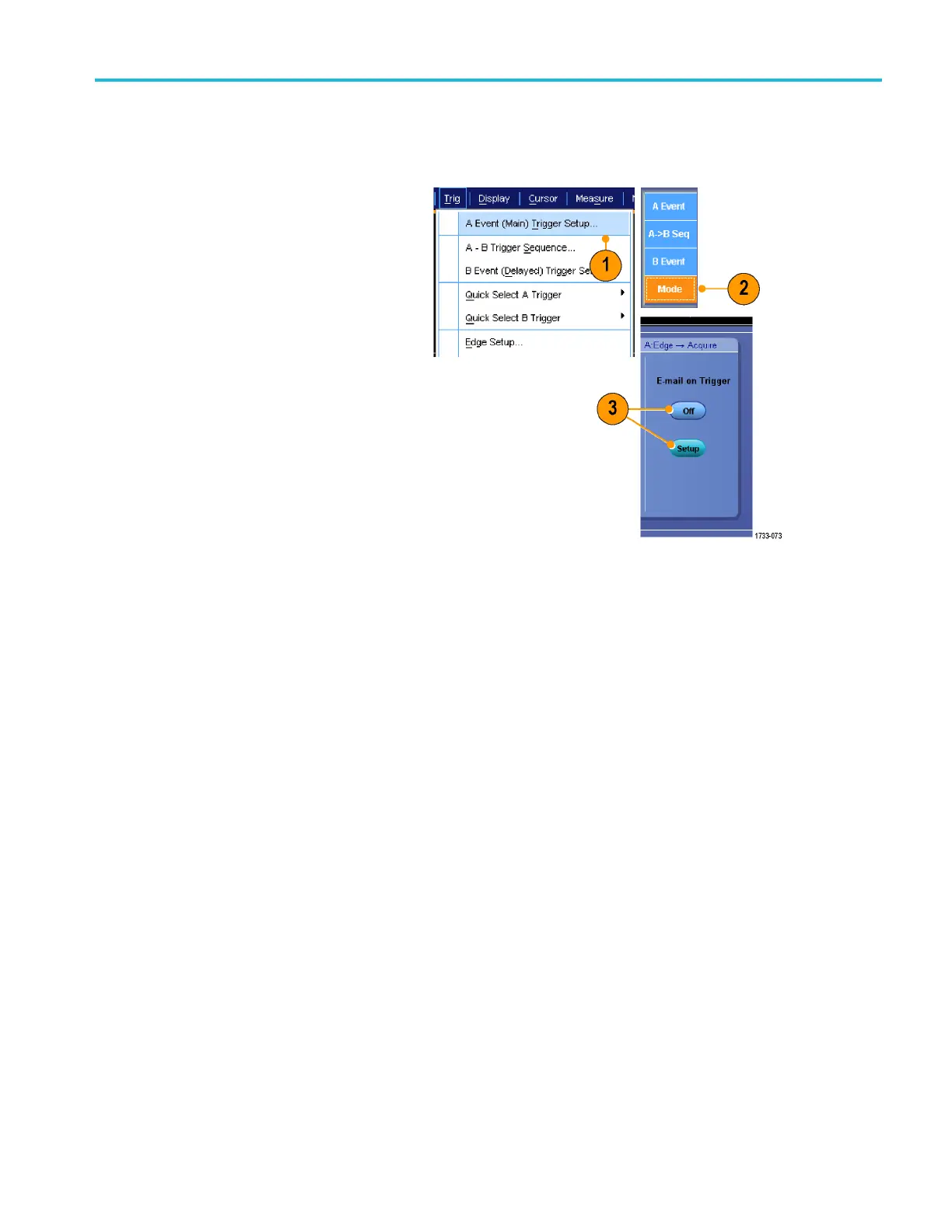
Covers A/B triggers, reset, bus triggering, visual triggers, and event actions.

Displaying Waveforms

Analyzing Waveforms

Automatic Measurements

Guides taking, customizing, and annotating automatic measurements.

Serial Data Analysis

Details using the Serial Error Detector for data analysis.

Signal Integrity Testing

Explains mask testing and limit testing procedures.

MyScope Customization

Application Examples

Appendix D: Logic Probe Instructions

Related product manuals