Pinpoint trigge
rs
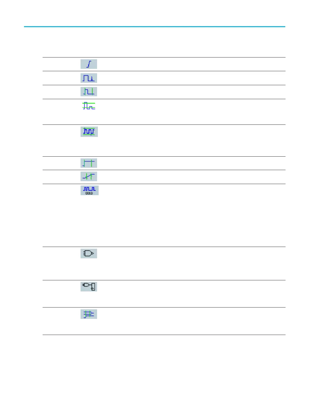
Trigger selections
Trigger Type Trigger Conditions
Edge
Trigger on a rising or falling edge, as defined by the slope control. Coupling choices
are DC, AC, LF R eject, HF Reject, and Noise Reject.
Glitch Trigger on a pulse narrower (or wider) than the specified width or ignore glitches
narrower (or
wider) than the specified width.
Width
Trigger on p
ulses that are inside or outside a specified time range. Can trigger
on positive or negative pulses.
Runt
Trigger on a pulse amplitude that crosses one threshold but fails to cross a second
threshold before recrossing the first. Can detect positive or negative runts, or only
those wide
r than a specified width. These pulses can also be qualified by the logical
state of other channels.
Window
Trigger when the input signal rises above an upper threshold level or falls below a
lower threshold level. Trigger the instrument as the signal is entering or leaving the
threshol
d window. Qualify the trigger event in terms of time by using the Trigger
When Wider option, or by the logical state of other channels using the Trigger When
Logic option.
Timeout
Trigger when no pulse is detected within a specified time.
Transition
Trigger on pulse edges that traverse between two thresholds at faster or slower rates
than the specified time. T he pulse edges can be positive or negative.
Serial Trigger on 64-bit NRZ serial pattern at data rates up to 1.25G b/s and 4 8b/10b
symbols at data rates up to 6.25Gb/s (MSO70000C/DX and DPO70000C/DX
only). Requires option ST1G (DPO7000C) or ST6G (MSO70000C/DX and
DPO70000C/DX). Includes clock recovery. Push the Push to Set 50% control to
reinitialize clock recovery.
Pattern Lock automatically finds and locks on a long repeating pseudo-random
bit sequence (PRBS). This lock means that the instrument knows the bit length of
the pseudo-random bit sequence and can predict when the cycle repeats. Pattern
Lock enables the instrument to take samples at s pecific locations in a data pattern
with outstanding time base accuracy.
Pattern
Trigger when logic inputs cause the selected function to become True or F alse. You
can also specify that the logic conditions must be satisfied for a specific amount of
time before triggering.
Not recommended with iCapture inputs if using more than one source or an external
trigger.
State Trigger when all of the logic inputs to the selected logic function cause the function to
be True or False when the clock input changes state.
Not recommended with iCapture inputs if using more than one source or an external
trigger.
Setup/ Hold
Trigger when a logic input changes state inside the setup and hold times relative to
the clock. The mode triggers on a setup and hold violation.
Not recommended with iCapture inputs if using more than one source or an external
trigger.
72 MSO/DPO70000DX, MSO/DPO70000C, DPO7000C, and MSO/DPO 5000B Series U ser M anual
 Loading...
