EasyManua.ls Logo

Tektronix DPO5104B User Manual

Tektronix DPO5104B
222 pages
To Next Page IconTo Next Page
To Previous Page IconTo Previous Page
Page #107 background image
Pinpoint trigge
rs
2. Click the area to enable its handles.
Click and drag the area to move it to a
new location.
Click and drag one of the area handles
to resize the area vertically, horizontally,
or both.
3. Right click in the visual trigger area
and select
Visual Trigger Area from the
menu.
Use the visual trigger menus to edit the
trigger ar
ea and set conditions for the visual
trigger.
Refer to online help for detailed information
about cre
ating and editing visual triggers.
4. From the
Trig menu, select Visual Trigger
Setup, then double click the Visual
Trigger equation.
Refer t
o online help for detailed information
about using the Qualication Expression
Editor.
MSO/DPO70000DX, MSO/DPO70000C, DPO7000C, and MSO/DPO5000B Series User Manual 85

Table of Contents

Other manuals for Tektronix DPO5104B

Question and Answer IconNeed help?

Do you have a question about the Tektronix DPO5104B and is the answer not in the manual?

Tektronix DPO5104B Specifications

General IconGeneral
Bandwidth1 GHz
Channels4
Vertical Resolution8 bits
Input CouplingAC, DC, GND
InterfaceUSB, GPIB, Ethernet
Operating Temperature0 °C to +50 °C
Sample Rate5 GS/s
Display Size12.1 inches
Display TypeXGA LCD
Input Impedance1 MΩ ± 1%, 13 pF ± 2 pF
Trigger ModesEdge, Video

Summary

Important Safety Information

General Safety Summary

Covers general safety precautions, fire/injury prevention, and operational guidelines.

Service Safety Summary

Provides critical safety information for qualified personnel performing product service procedures.

Compliance Information

Install Your Instrument

Installation Procedures

Covers ESD prevention, power management, securing, networking, and OS restore for instrument setup.

Acquisition

Signal Path Compensation and Setup

Covers signal path compensation, analog signal input setup, and probe compensation/deskew.

Acquisition Modes and Concepts

Explains sampling processes, record building, and acquisition modes like Sample, Peak, Envelope, and Average.

Digital Signal Analysis Features

Details setting up digital channels, buses, MagniVu, iCapture, FastFrame, and FastAcq for detailed analysis.

Pinpoint Triggers

Triggering Fundamentals

Covers trigger concepts, modes, holdoff, coupling, and horizontal position for precise triggering.

Trigger Types and Selections

Details various trigger types (Edge, Glitch, Serial, Bus) and their conditions for signal analysis.

Advanced Triggering and Actions

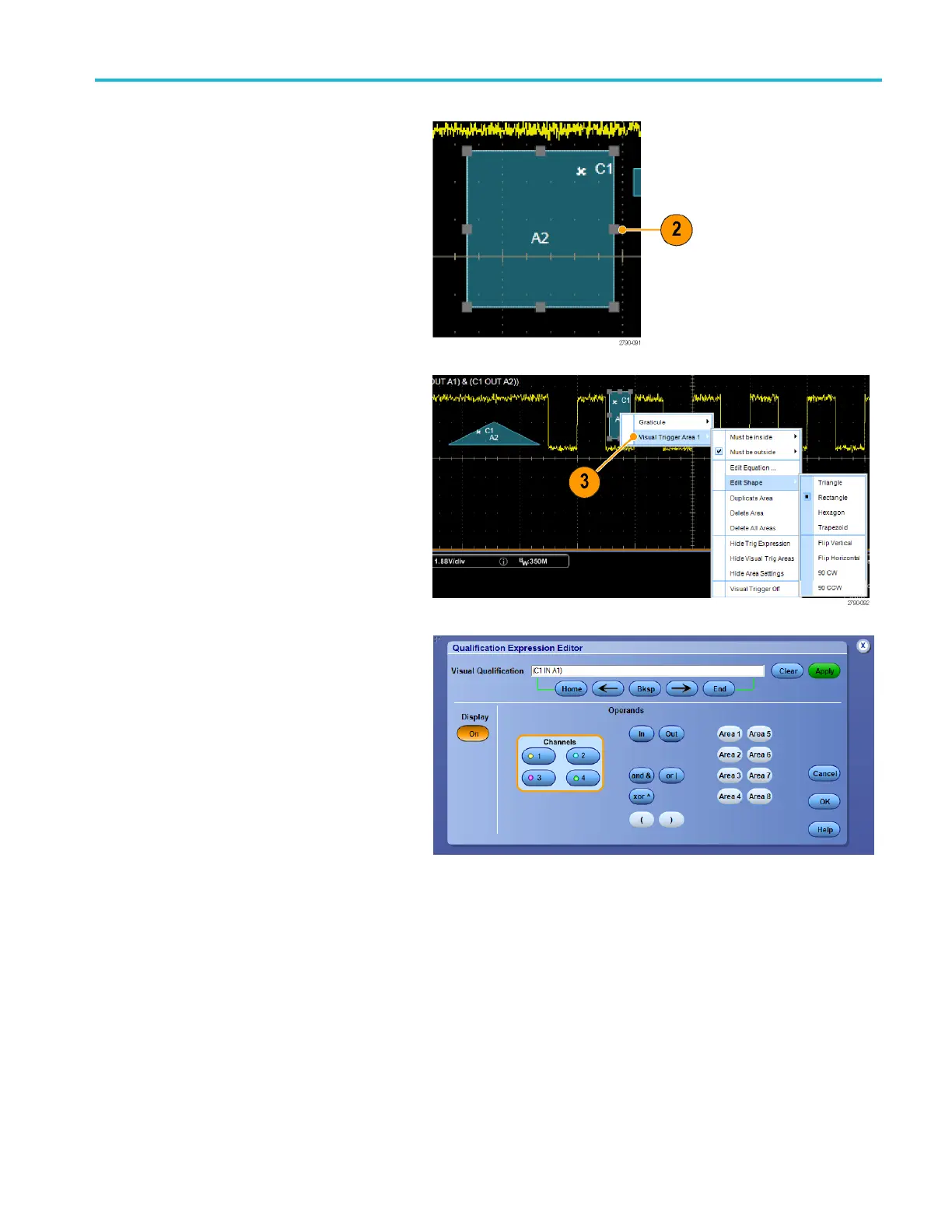
Explores B-Event Scan, bus triggering, visual triggers, and action-on-event for complex signal analysis.

Display a Waveform

Analyzing Waveforms

Measurements and Statistics

Covers automatic measurements, statistics, annotations, reference levels, and cursors.

Math, Spectral, and Serial Analysis

Explains math waveforms, spectral analysis, serial error detection, mask, and limit testing.

MyScope

Application Examples