Install your ins
trument
7. Maximum input
voltage, DPO7000C
models:
50 Ω
1MΩ
5V
RMS
,withno
impulse allowed, with peaks ≤±24 V.
150 V, derate at 20 dB/decade to 9 V
RMS
above 200 kHz. The maximum
input voltage at the BNC, between center conductor and ground is
400 V peak. Th
e RMS voltage is limited to <150 V for arbitrary waveshapes
including DC. The maximum pulse width for impulses w ith peaks over
150Vis50μs. Example: At 0 V to 400 V peak, rectangular wave, the duty
factor is 14
%. The maximum transient withstand voltage is ±800 V peak.
Maximum inp
ut voltage, 4 GHz to 20 GHz
models:
50 Ω <1 V
RMS
for <1 V/F S settings and < 5.5 V
RMS
for ≥1 V/FS settings.
Maximum input voltage, > 20 GHz models:
50 Ω≤1.2 V/FS settings:
±1.5 V relative to the termination bias (30 mA maximum).
±5 V abso
lute maximum input.
>1.2 V/FS settings:
10 V at 25 °C derated to 8.4 V at 45 °C (limited by attenuator).
Maximum nondestructive input voltage to
logic probes, MSO 70000C/DX Series:
±15 V
CAUTION. For proper cooling, keep the bottom and sides of the instrument clear of obstructions.
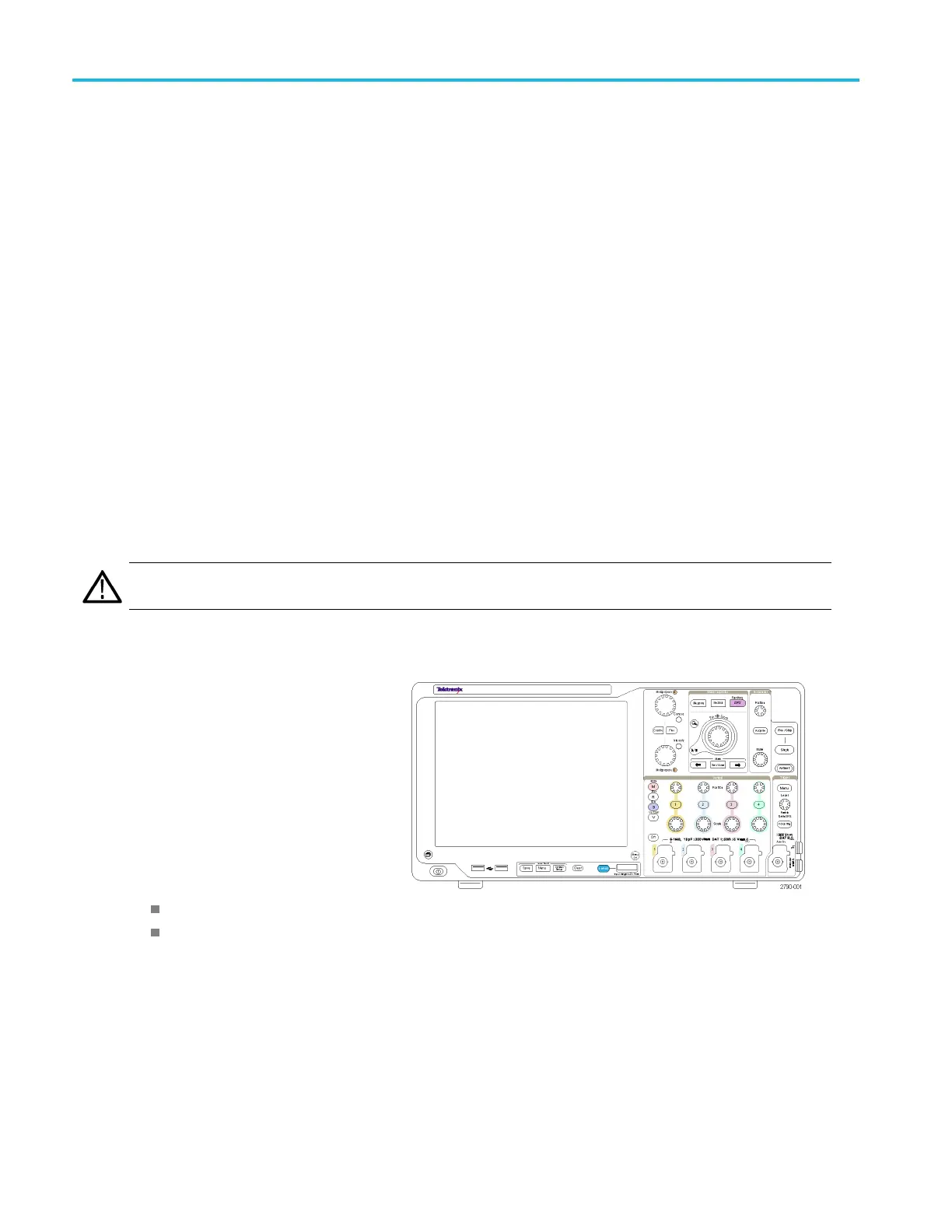
MSO5000B and DPO5000B
1. Place the instrument on a cart or bench.
The instrument should rest on its bottom
or rear feet. An optional rack mounting
kit is available. Observe the following
clearance requirements and dimensions:
Rear:
2in(50.8
mm)
Left side
:
2in(50.8
mm)
2. Width:
17.3 inc
hes (439 mm)
3. Height:
9.2 inch
es (233 mm) including feet
10.7 inches (272 mm) including vertical handle and feet
4. Before operating the instrument, verify
the ambient temperature:
5°Cto+50°C(+41°Fto+131°F)
4 MSO/DPO70000DX, MSO/DPO70000C, DPO7000C, and MSO/DPO 5000B Series U ser M anual
 Loading...


