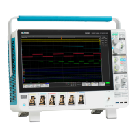
Carrier interface assembly
The Carrier interface assembly contains the following functions:
Processor system The processor system contains a microprocessor that controls the entire instrument. The processor system
also contains the solid state drive for the operating system, system RAM, and interfaces to I/O ports and the
acquisition system.
Rear panel I/O ports The Carrier interface assembly contains USB ports, an Ethernet port (LAN), a VGA Video port, a DVI Video
port, a DisplayPort V
ideo port, the USB-TMC port, an AUX OUT BNC connector, an EXT REF IN BNC
connector, and the AFG Out generator BNC connector.
Power converter The Carrier interface assembly converts the +12 V power to all voltages used for the analog and digital
circuitry throughout the system. Standby power is used to keep portions of the Carrier interface assembly
and Main board powered at all times that AC power is connected to the instrument.
Other functions The Carrier interface assembly also houses the AFG generator, USB-TMC controller and interfaces to the
Power supply and various cooling fans. The Carrier interface assembly also provides the interface to the
optional Windows drive.
Main board and front-end board
The Main and Analog boards contain the following functions:
Acquisition system The Acquisition system begins with the analog signal path and ends with a digitized signal in memory. The
signal enters a channel input, and then passes through an attenuator and preamplifier. The analog signal
from each preamplifier goes through a digitizer, and then into acquisition memory. The analog signal from
each preamplifier is also distributed to a trigger circuit.
Front-end All of the analog and digital inputs are routed to the Front-end board. The analog channels are amplified
and attenuated through the front-end circuitry, and are output to the Main board. The digital channels simply
pass through the front-end board to the Main board. The front-end board has a controller that is used as an
I/O controller for the front-end board.
Power converter The Main board converts the +12 V power to some of the other voltages used for the analog and digital
circuitry throughout the system. This is in addition to the power conversion provided by the Processor
assembly.
Front panel and display
The Front Panel board contains digital logic that reads the front-panel buttons and controls and sends this information to the processor
system on the Processor assembly
. The Front Panel board also generates the probe compensation output signal, provides USB ports
on the front panel and houses the main power switch. The front panel routes the digital front-end signals from the probe directly to the
front-end board. The front panel also provides the video interface to the internal HD display.
Theory of operation
5 Series MSO Service Manual MSO54, MSO56, MSO58 13

 Loading...


