Operator Information
P6021 Instruction Manual
5
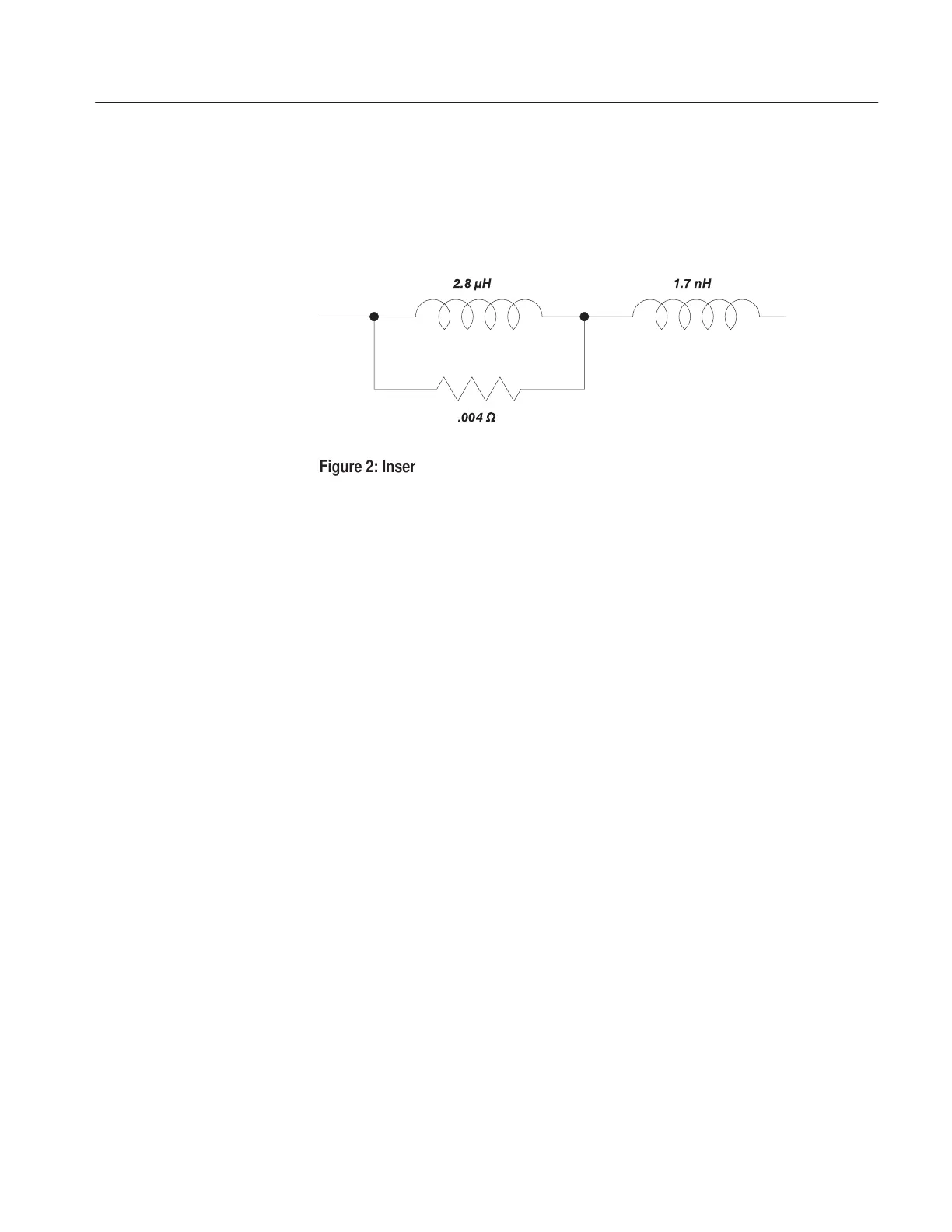
When you insert a conductor into the probe, you add impedance to the circuit
you are measuring. This additional impedance affects signals; this is particularly
important if you are measuring fast rise times. Figure 2 illustrates the equivalent
circuit with the additional impedance introduced by the P6021.
.004
W
1.7 nH2.8
m
H
Figure 2: Insertion Impedance of the P6021
To minimize the loading effect of the probe, clamp it at the low or ground end of
a component lead when possible. This method also minimizes noise or stray
signal interference.
You can increase the current sensitivity of the probe by increasing the number of
times a conductor passes through it. For example, if the conductor loops through
the probe twice (a two-turn primary winding), the secondary current is doubled.
For example, suppose you set the termination sensitivity to 2 mA/mV and the
oscilloscope vertical scale to 10 mV/division. Ordinarily, this would result in the
equivalent of 2 X 10, or 20 mA/division. However, if the conductor is looped
through the probe twice, the vertical scale is divided by two, resulting in the
equivalent of 10 mA/division.
Looping the conductor twice effectively doubles vertical sensitivity; however,
impedance from the probe winding is also reflected into the circuit being
measured. This impedance is proportional to the square of the number of loops.
This additional impedance affects signals; this impedance is particularly
important when you are measuring high-frequency current waveforms or
waveforms with fast rise times.
Insertion Impedance
Minimizing Loading Effect
Increasing Probe
Sensitivity

 Loading...


