TAS 200 Series Adjustment Procedures
28
Bench Test Instruments and Handheld Oscilloscopes Basic Service
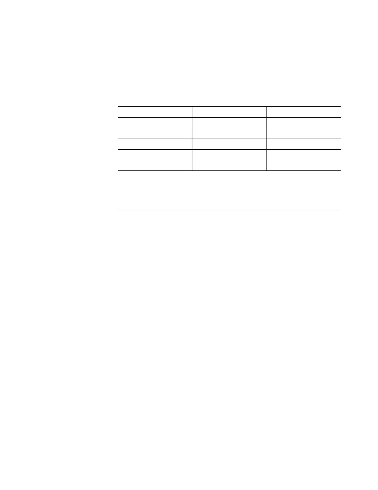
4. Verify that the voltage levels in Table 21 are within the specified limits. See
Figure 7 for the test point locations.
Table 21: Power supply limits
Power supply Test point Limits (volts)
+12 +12 +11.95 to +12.05
-- 1 2 -- 1 2 --11.80 to --12.20
+5 +5 +4.75to+5.25
+185 (TAS 220) +185 +180 to +190
+145 (TAS 250) +145 +140 to +150
NOTE. If a power supply measurement exceeds the limits specified in Table 21,
discontinue the adjustment procedures. C ontact a Tektronix service center for
instrument repair.
5. Disconnect the voltmeter from the instrument.
Use the following procedure to adjust the display intensity.
1. Set up the oscilloscope as follows:
HORIZONTAL SEC/DIV 1 ms
TRIGGER HOLDOFF NORM
2. Rotate the front panel INTENSITY control to the fully counterclockwise
position; then rotate the control clockwise to the 90_ (nine o’clock) position.
3. Locate VR603 on the Power and High Voltage board (see Figure 7 for the
adjustment location). Adjust VR 603 until the trace is barely visible.
4. Rotate the INTENSITY control clockwise. Verify that the trace becomes
brighter. Rotate the INTENSITY control fully counterclockwise; the trace
should disappear.
Use the following procedure to adjust the display focus and astigmatism.
1. Set the front panel FOCUS control to midrange; then adjust VR602 on the
Power and High Voltage board to obtain the best focus. See Figure 7 for the
adjustment location.
2. Set the front panel HORIZONTAL X-Y push switch to the in position.
Intensity
Focus and Astigmatism
 Loading...

