Troubleshooting and Error Codes
Displaying Er
ror Codes with the Probe Degauss Autobalance Button
This section describes the err or codes that the amplifiers d isplay using the
function indicator LEDs.
When an internal error condition e xists, the amplifiers may generate error codes.
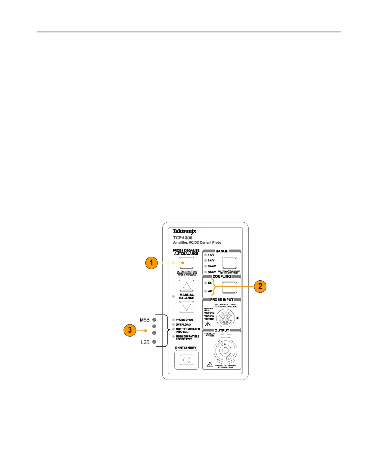
To display the error codes, do the following. (See Figure 26.)
1. Press the PROBE DEGAUSS AUTOBALANCE button.
2. The AC and DC Coupling LEDs will flash alternately to indica t e that error
codes are being displayed instead of normal conditions.
3. The four fault indicator LEDs above the ON/STANDBY switch are used to
form a four-bit binary error code. (See Figure 27 on page 46.) The error codes
are defined in the table. (See Table 7 on page 46.)
The PROBE OPEN LED indicates the most significant bit (MSB), and the
NONCOMPATIBLE PROBE TYPE LED indicates the least significant bit
(LSB).
4. To continue past an e rror code , press any button except ON/STANDBY.
Howev
er, the degauss will fail until the internal error condition is c orrected
and the degauss operation is run again.
Figure 26: Error code display
TCPA300/400 Amplifiers and TCP300A/400 Series Current Probes User Manual 45
 Loading...


