Performance Tests
4-38
TDS 420A, TDS 430A & TDS 460A Service Manual
Trigger System Checks
These procedures check those characteristics that relate to the Main and Delayed
trigger systems and are listed as checked under Warranted Characteristics in
Chapter 1, Specification.
Equipment
Required
One DC calibration generator (Item 10)
One BNC T connector (It em 8)
Two precision coaxial cables (Item 5)
Prerequisites See page 4--15.
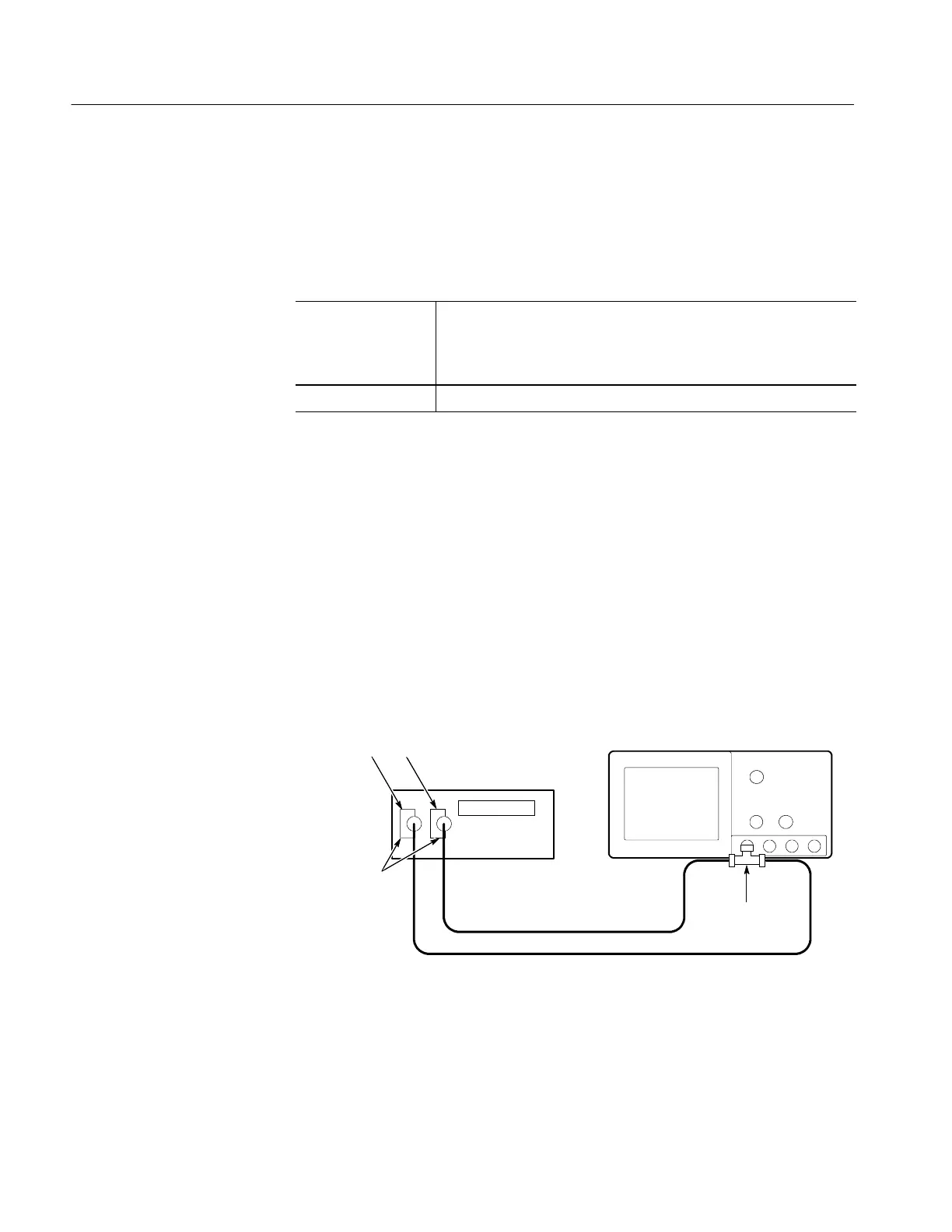
1. Install the test hookup and preset the instrument controls:
a. Hook up the test-signal source:
H Set the output of a DC calibration generator to 0 volts.
H Connect the output of a DC calibration generator through a
dual-banana connector followed by a 50 Ω precision coaxial cable to
one side of a BNC T connector.
H Connect the Sense output of the generator, through a second
dual-banana connector followed by a 50 Ω precision coaxial cable,
to the other side of the BNC T connector. Now connect the BNC T
connector to CH 1 (see Figure 4--12).
Digitizing Oscilloscope
DC Calibrator
50 Ω Coaxial Cables
Dual Banana to
BNC Adapters
BNC T
Connector
Output Sense
Figure 4- 12: Initial Test Hookup
b. Initialize the oscilloscope:
H Press save/recall Setup.
Check Accuracy, Trigger
Level or Threshold, DC
Coupled

 Loading...


