Specifications
1-2
TDS1000 and TDS2000 S eries Digital Storage Oscilloscopes Service Manual
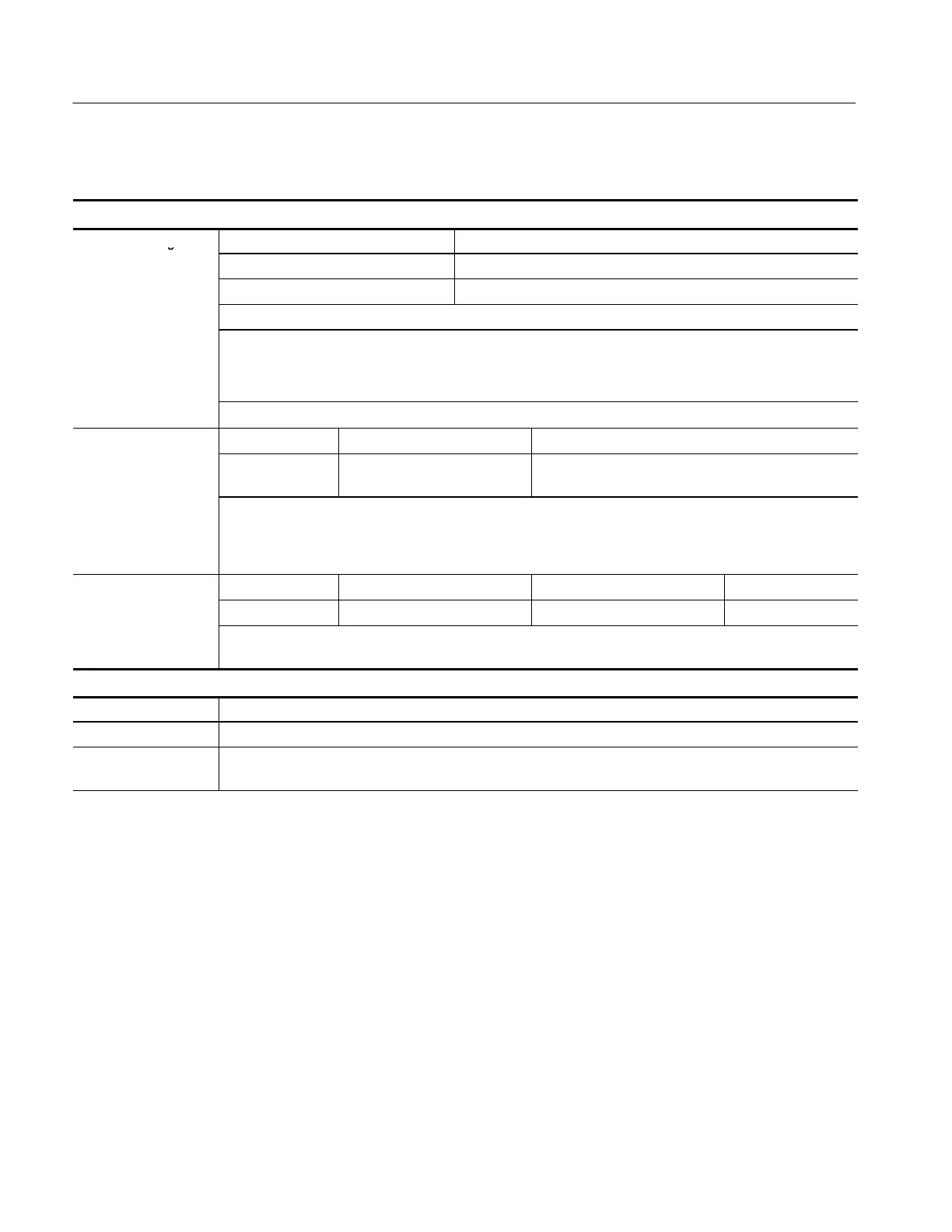
Table 1- 1: Oscilloscope specifications (Cont.)
Inputs
Maximum Voltage Overvoltage Category* Maximum Voltage
Between Signal and
CAT I and CAT II 300 V
RMS
ommon
npu
CAT III 150 V
RMS
Derate at 20 dB/decade above 100 kHz to 13 V peak AC at 3 MHz and above.
For non-sinusoidal waveforms, peak value must be less than 450 V. Excursion above 300 V should be less
than 100 ms duration.
RMS signal level including any DC component removed through AC coupling must be limited to 300 V.
t
ese
ues
re e
ee
e
,
m
ge to t
eos
os
ope m
resu
t.
Channel-to-Channel TDS1001 TDS1002, TDS2002, TDS2004 TDS1012, TDS2012, TDS2014, TDS2022, TDS2024
Common Mode
Rejection, t ypical
100:1 at 60 Hz
20:1at20MHz
100:1 at 60 Hz
20:1at30MHz
100:1 at 60 Hz
10:1at50MHz
Measured on MATH Ch1 -- Ch2 waveform, with test signal applied between signal and common of both
channels, and with the same VOLTS/DIV and coupling settings on each channel
Measured on MATH Ch3 -- Ch4 waveform for 4-channel model s
Channel-to-Channel TDS1001 TDS1002, TDS2002, TDS2004 TDS1012, TDS2012, TDS2014 TDS2022, TDS2024
Crosstalk
≥ 100:1 at 20 MHz ≥ 100:1 at 30 MHz ≥ 100:1 at 50 MHz ≥ 100:1 at 100 MHz
Measured on one channel, with test signal applied between signal and common of the other channel, and
with the same VOLTS/DIV and coupling settings on each channel
Vertical
Digitizers 8-bit resolution (except when set to 2 mV/div), each channel sampled simultaneously
VOLTS/DIV Range 2 mV/div to 5 V/div at input BNC
Position Range 2 mV/div to 200 mV/div, ±2V
> 200 mV/div to 5 V/div, ±50 V
*
Refer to the Overvoltage Category description on page 1--10.
 Loading...

