Maintenance
6-- 20
TDS1000 and TDS2000 Series Digital Storage Oscilloscopes Service Manual
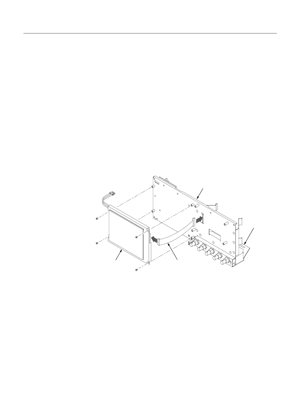
Installation. To install the display cable, refer to Figure 6--11 and follow these
steps:
1. Remove the display module using the procedure on page 6--24.
2. Attach the display cable to the appropriate connector on the display module
at the location shown in Figure 6--11: 12-pin for the monochrome display,
and 15-pin for the color display.
3. With the display module in place but not connected, thread the display cable
through the appropriate slot on the chassis.
4. Twist the cable two revolutions to keep it from contact with the boards and
chassis, and secure using the left cable tie.
5. Connect the display cable at J201 on the main board by pushing the cable
straight down into the connector.
6. Install the four screws to attach the display module to the internal assembly.
Internal
assembly
Main
board
Display cable
Display
module
Figure 6--11: Installing the display cable
 Loading...

