Maintenance
Display Adapter Module
You will need a t
orque-limiting Torx T-15 screwdriver and pliers for this
procedure.
Refer to the ex
ploded v iew diagram. (See page 8-8.)
Removal.
1. Remove the p
ower button and rear case. (See page 6-10, Rear Case.)
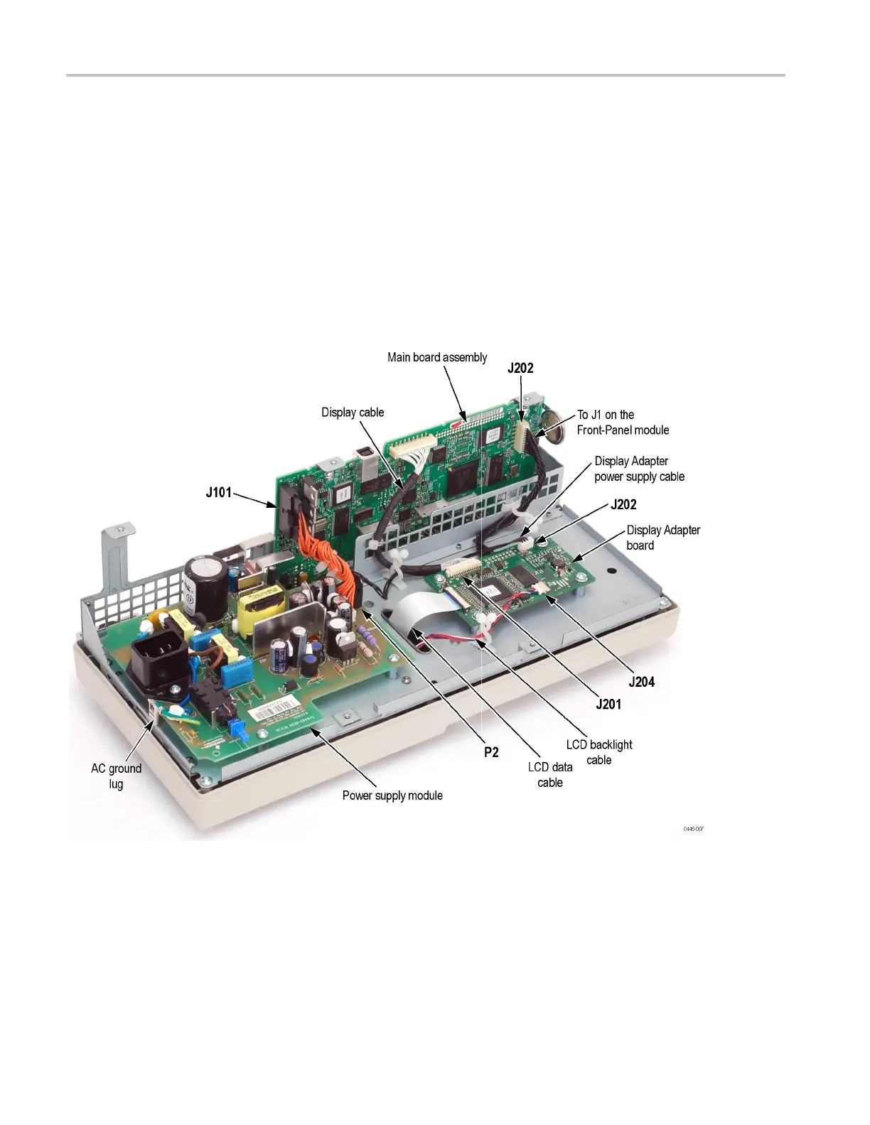
2. Disconnect the Display cable from J201 on the Main board by pulling straight
up from the
connector. Remove the cable tie to release the cable. (See
Figure 6-3.)
Figure 6-3: Display Adapter board connections
3. Disconnect the LCD data cable from the Display Adapter board.
4. Disconnect the LCD backlight cable from the Display Adapter board at J204.
5. Disconnect the Display Adapter board power cable from the Display Adapter
board at J202.
6–14 TDS2000C Series Oscilloscope Service Manual
 Loading...

