Maintenance
6-- 36
TDS1000 and TDS2000 Series Digital Storage Oscilloscopes Service Manual
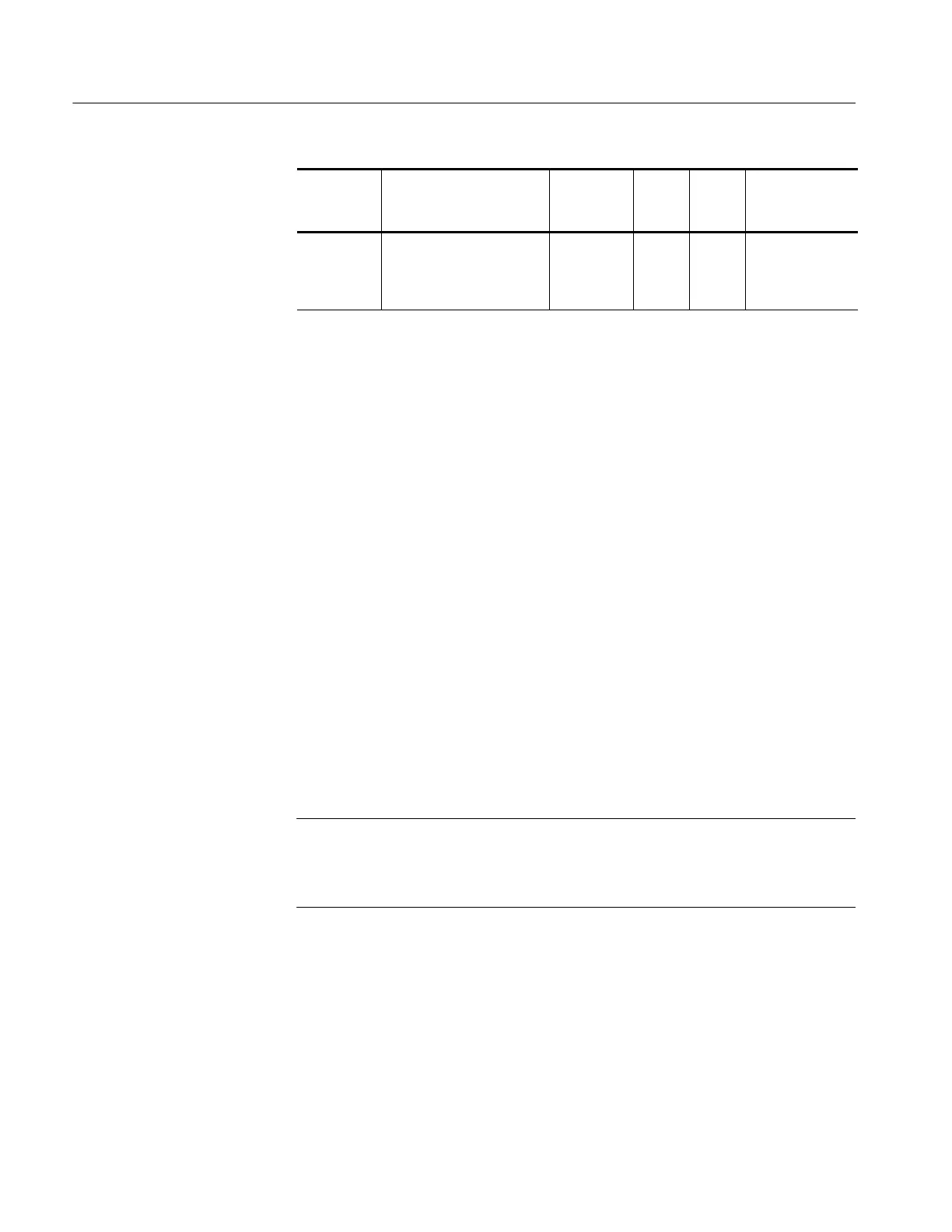
Supply
Derived
supplies
J101
return
pins
J101
power
pins
Maximum
Current
Draw
Voltage range*
Backlight
(mono-
chrome or
color)
>500 V
pk-pk
, ∼50 kHz NA NA NA
*
With 3 W minimum load; still functions with no load.
3. If all of the voltages are present, the main board is probably defective.
Replace it.
4. If all or some of the voltages are missing, turn off the oscilloscope and
disconnect the cable at connector J101 on the main board module.
5. Turn on the oscilloscope and check the voltages at the loose end of the cable
disconnected from J101, checking for the same voltages as in step 2.
6. If all of the voltages are missing, check the line fuse on the power supply
module. If the fuse is defective, replace the power supply module.
7. If the fuse is okay, and all or some of the voltages are missing, the power
supply module is probably defective. Replace it.
To troubleshoot a nonfunctional display, follow these steps:
1. Remove the rear case using the procedure Rear Case on page 6--10.
2. Turn on the oscilloscope and ensure that the display lights up. If it does not,
either the display or power supply is defective. If this procedure is not
conclusive, continue with Troubleshooting the Power Supply on page 6--35
NOTE. Without a functional display module, the simplest way to verify that the
oscilloscope is on and functioning is to check for a signal at the PROBE COMP
output. The PROBE COMP output generates approximately a 5 V, 1 kHz square
wave.
3. Use the test oscilloscope and set the Attenuation switch to 10X on the P2200
probe to probe the display cable connector at J201 on the main board. The
following table describes the signals you should expect to see. See the
Troubleshooting the
Display
 Loading...

