Reference
Bottom
Side
Description
Level (Input 1) N
Level (Input 2) N
Sets the threshold voltage level for input 1 and
2 to level N, using the general purpose knob .
Set to TTL Sets the threshold voltage level to 1.4 V for
both inputs.
Set to ECL Sets the threshold voltage level to -1.3 V for
both inputs.
Thresholds
Set to 50% Sets the threshold v
oltage level to 50% of each
input's peak-to-
peak value.
Mode &
Holdoff
The table on Edge triggering includ es a
description of this menu item. (See page 114.)
Key Points
Trigger When. The input cond ition m ust b e tru e o r false for ≥2nsin
order for the oscilloscope to detect the patte rn.
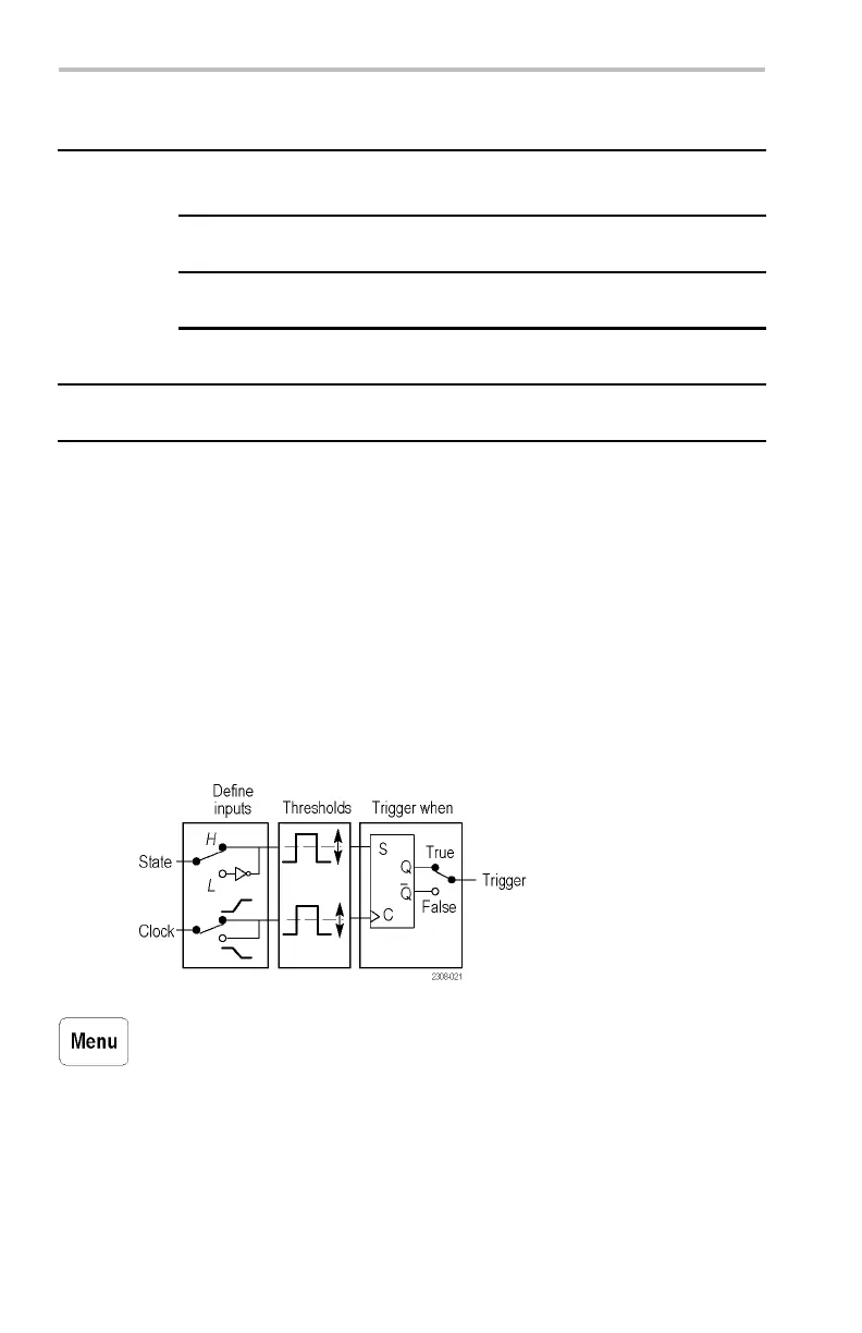
State Trigger
State triggering triggers the oscilloscope when a state sign al is true or
false at the tim e a clock signal transition is true. This trigger is useful
for troubleshoo tin g digital logic synchronous state mach ines.
Stat
e Trigger Conditions
Push the Trigger Menu bu tto n, and then push the Type bottom screen
button to select Logic. The next table lists the menu items when the
trigger Type is set to Logic, and the C lass is set to State.
122 TDS3000C Series Oscilloscope User Manual
 Loading...