Installation Instructions
16
WVR6UP, WVR70UP, and WVR7UP Upgrades
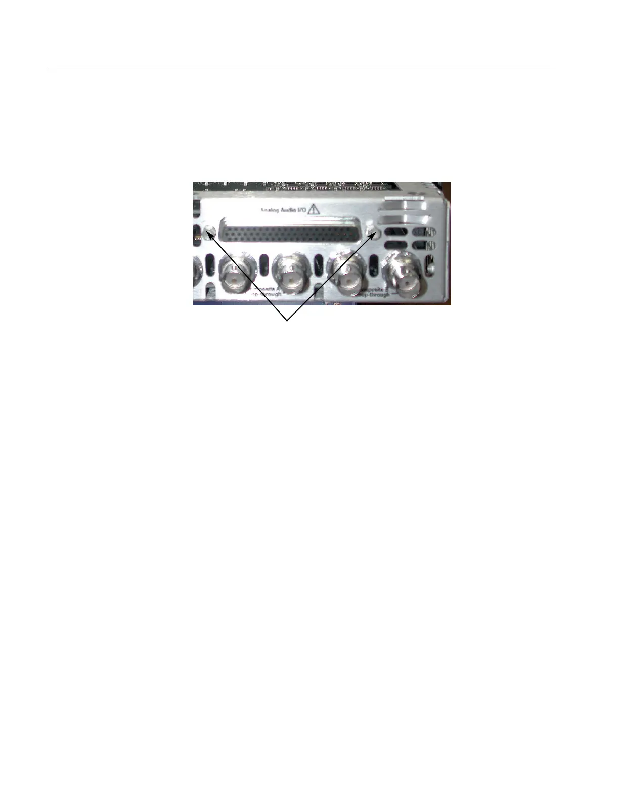
9. For all Audio boards except options WVR6UP-DS, WVR70UP-DS, and
WVR7UP-DS, install the two standoff retainers that secure the audio analog
connector to the rear panel. These screws install from the outside of the rear
panel. Tighten firmly, but not excessively.
Install stand-off retainers
10. Reinstall the top cover on the instrument.
For all audio options except WVR6UP-DS, WVR70UP-DS, and WVR7UP-DS,
use the supplied 62-pin DSUB connector to attach analog-audio signals to the
instrument. Solder wires to the connector as needed to accommodate the desired
audio inputs and outputs. Refer to the WVR6100, WVR7000, and WVR7100
Waveform Rasterizers Quick Start User Manual for the connector pin assign-
ments.
Audio signals can be connected as either balanced or unbalanced. Be sure to use
a suitable cable when you are wiring balanced audio. An example of a suitable
cable is Belden 8451, which is a shielded twisted-pair cable.
Alternatively, you can purchase an audio breakout cable (Tektronix part number
012-1688-00), which provides a two-meter cable with XLR connectors for all
twelve inputs and eight outputs.
Audio Connector
 Loading...