46 www.behnke-online.de
GB
Instructions for Behnke SIP 2.0
Installation
Please note: When placing the function modules,
please take note of the direction of the alumin-
ium brushing both for aesthetic reasons and for
dampness protection and also follow the anti-
twist protection of the modules! The door inter-
com station may only be installed with a suitable
frame. Prevent any condensation from forming
inside the housing! Mount the door intercom
station in a way, that water will not remain on the
front cover. When mounting your door intercom
into a third-party column, please pay special
attention to the column ventilation.
When installing the electronics in a locally remote
mounting, please replace the module housing
with open counterplate for the respective front
frame (use button extension 20-9305, do not
extend the connection wires yourself, max 3m).
Connect the wires in the following sequence:
1. Buttons (RT)
▸
to the MQS plugs marked with
the from T1 to T8. When using third-party but-
tons, please ensure, that the button meets
the corresponding licensing requirements.
“Bell buttons” usually do not meet these
requirements (cf. page 70). The buttons
need to be potential-free. These buttons are
known as direct call buttons in the web fron-
tend of your SIP door intercom. T1 = button 1,
T2 = button 2, etc.
2.
installation
Please note: Measurement and installations
sketches are available at
www.behnke-online.de/bemassung
2. Speaker (LP)
▸
to the plug marked with the
blue ring (SIP door intercom stations require an
8 Ohm speaker)
3. Microphone (Mik)
▸
to the plug marked with
the white ring
4. Key pad
▸
white 12-pin socket
5. Camera
▸
connect to port 2 of the SIP door
intercom, where necessary Please take note
of the Switchport technical data for third-party
cameras.
6. Please connect the open door function to relay
1, where necessary. (Relay = a potential-free
contact: only switches the circuit to open the
door, but does not provide electric voltage.
Please use the make contact to do so). The
door open function requires its own circuit.
Relay 2 is available for additional switch
functions. Default setting for relay activation on
relay 1 of your SIP door intercom: 0#
7. Please connect the SIP door intercom to your
own network infrastructure while maintaining
the corresponding norms and regulations of
network technology.
Important: PoE Class 0 is required! PoE Plus
is required for an SPL intercom station (page
53).
8. Inside the module housing, please mount the
unused wires of the ribbon cable with their
open end (plug) facing down. When using
third-party housings and columns, this will
prevent dampness from condensation entering
into the plug. Then put the electronics box onto
the module housing.
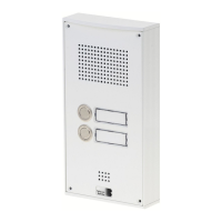
2.1. Series 20 / 30 / 40 / 50 (20-0001A-IP, 20-0002A-IP, 20-0013A-IP, 20-0014A-IP,
20-0016A-IP, 20-0041A-IP, 20-0043A-IP)
 Loading...