59www.behnke-online.de
GB
Instructions for Behnke SIP 2.0
Hardware
8.
hardware
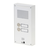
8.1. Compact devices Series 5/10
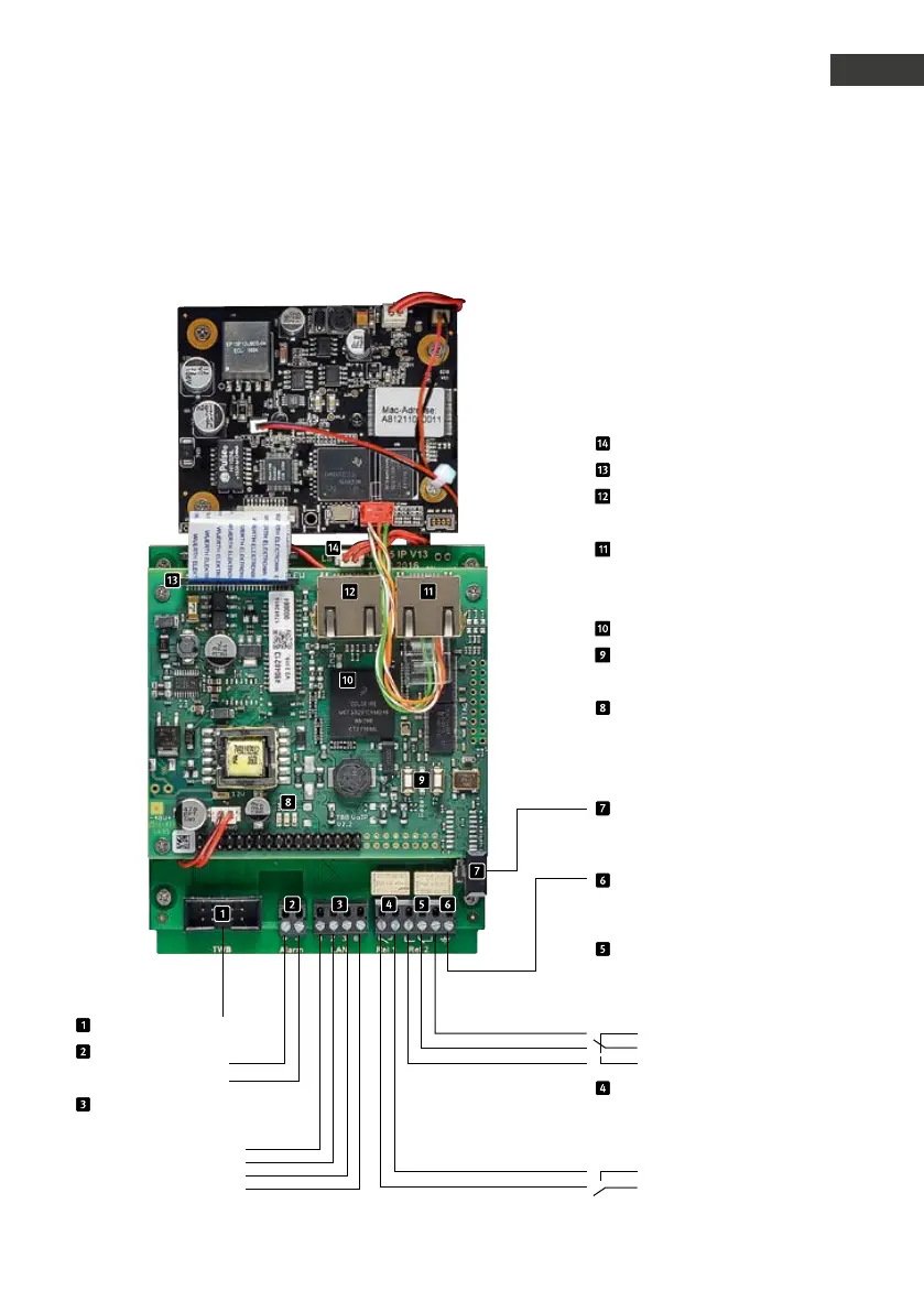
1: white-green
2: green
3: white-orange
6: orange
Ethernet connection
according to EIA/TIA 568 A
Earthing
needed in case a TNV-1 circuit is used
(e.g. devices to be mounted in a column
without connection to the building)
Connection speaker
Connection for extensions
LAN receptacle INPUT
(SIP intercom station to Switch)
Network connection PORT 2
(receptacle for additional IP devices,
e.g. an IP camera. Please adhere to the
technical data of the Switchport).
Master CPU
T1 + T2
Buttons to display device information (cf.
p. 55)
LEDs:
Red: Power supply PoE
(LED illuminated: PoE available)
blue: ready
(LED flashing Device “booting”)
(max 5 min)
Green: Registered on SIP server
Tamper contact
(not activated in default status, can be
activated via the web frontend, please see
the “Help” section in the webf rontend)
Relay 2
max. switching voltage: 60VDC/50VAC
max. switching current: 2A
max. switching cable max 62,5VA/60W
Please note that none of the above
specifications may be exceeded
Relay 1
max. switching voltage: 60VDC/50VAC
max. switching current: 2A
max. switching cable max 62,5VA/60W
Please note that none of the above
specifications may be exceeded
Rest contact
Control contact
Make cotact
5VDC – 18VDC
Alarm input
Connection codelock
–
+
Make contact
Control contact
 Loading...