www.ti.com
Hardware
13
SWRU508B–May 2017–Revised April 2018
Submit Documentation Feedback
Copyright © 2017–2018, Texas Instruments Incorporated
AWR1642 Evaluation Module (AWR1642BOOST) Single-Chip mmWave
Sensing Solution
2.7 Jumpers, Switches, and LEDs
2.7.1 Sense-on-Power (SOP) Jumpers
The AWR1642 device can be set to operate in three different modes based on the state of the SOP lines.
These lines are sensed only during boot up of the AWR device. The state of the device is detailed by
Table 4.
A closed jumpers refers to a 1, and an open jumper refers to a 0 state of the SOP signal going to the
AWR device.
Table 4. SOP Jumper Information
Reference Usage Comments
P3 SOP 2
SOP[2:0]
101 (SOP mode 5) = flash
programming
P2 SOP 1
001 (SOP mode 4) =
functional mode
P4 SOP 0
011 (SOP mode 2) = dev
mode
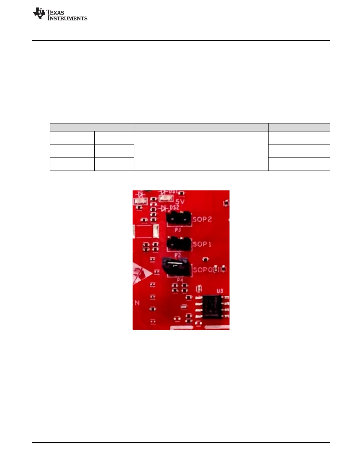
Figure 12 shows the SOP jumpers.
Figure 12. SOP Jumpers
 Loading...