Hardware
www.ti.com
6
SWRU508B–May 2017–Revised April 2018
Submit Documentation Feedback
Copyright © 2017–2018, Texas Instruments Incorporated
AWR1642 Evaluation Module (AWR1642BOOST) Single-Chip mmWave
Sensing Solution
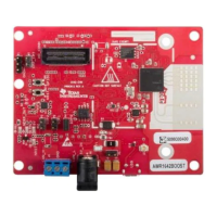
2.2 Power Connections
The BoosterPack is powered by the 5-V power jack (5-A current limit), shown in Figure 4. As soon as the
power is provided, the NRST and 5-V LEDs should glow, indicating that the board is powered on.
NOTE: After the 5-V power supply is provided to the EVM, it is recommended to press the NRST
switch (SW2) one time to ensure a reliable boot-up state.
Figure 4. Power Connector
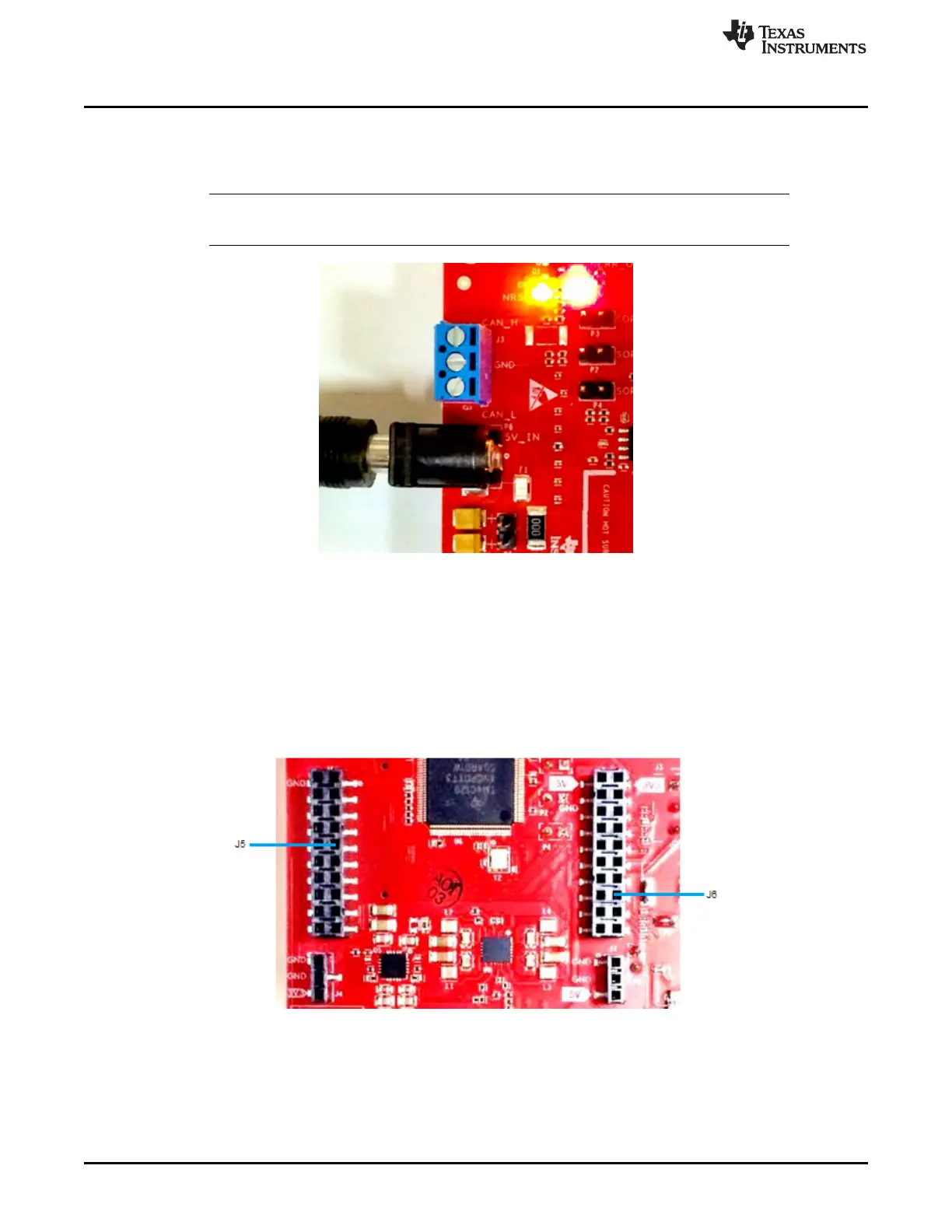
2.3 Connectors
2.3.1 20-Pin BoosterPack Connectors
The BoosterPack has the standard LaunchPad connectors (J5 and J6, shown in Figure 5) that enable it to
be directly connected to all TI MCU LaunchPads. While connecting the BoosterPack to other LaunchPads,
ensure the pin-1 orientation is correct by matching the 3V3 and 5-V signal marking on the boards.
Figure 5. 20-Pin BoosterPack Connectors
 Loading...