AWR1642
BP Connector
XDS110
CANFD
SOP
PC Interface
through USB
UART and JTAG
SPI, UART, I
2
C,
Rst, Nerrs,
SOPs, Loggers,
CAN, and GPIOs
60-pin HD
LVDS data and Clk
JTAG and trace
40-Mhz
XTAL
QSPI
Flash
Optional for 3.3-V
from MCU
LaunchPad
TM
PMIC
LDO1
4 RX and 2 TX PCBs
LDO2
1.8 V
1.3 V
1.2 V
3.3 VIO
1.8 V
2.3 V
EN control from the
MCU
PGOOD signal to
MCU for power
sequencing
5-V input
from jack
and MCU
Power and 2 GPIO
LED indicators
Control signals for
external MCU interface
Current
measurement
Copyright © 2017, Texas Instruments Incorporated
www.ti.com
Hardware
5
SWRU508B–May 2017–Revised April 2018
Submit Documentation Feedback
Copyright © 2017–2018, Texas Instruments Incorporated
AWR1642 Evaluation Module (AWR1642BOOST) Single-Chip mmWave
Sensing Solution
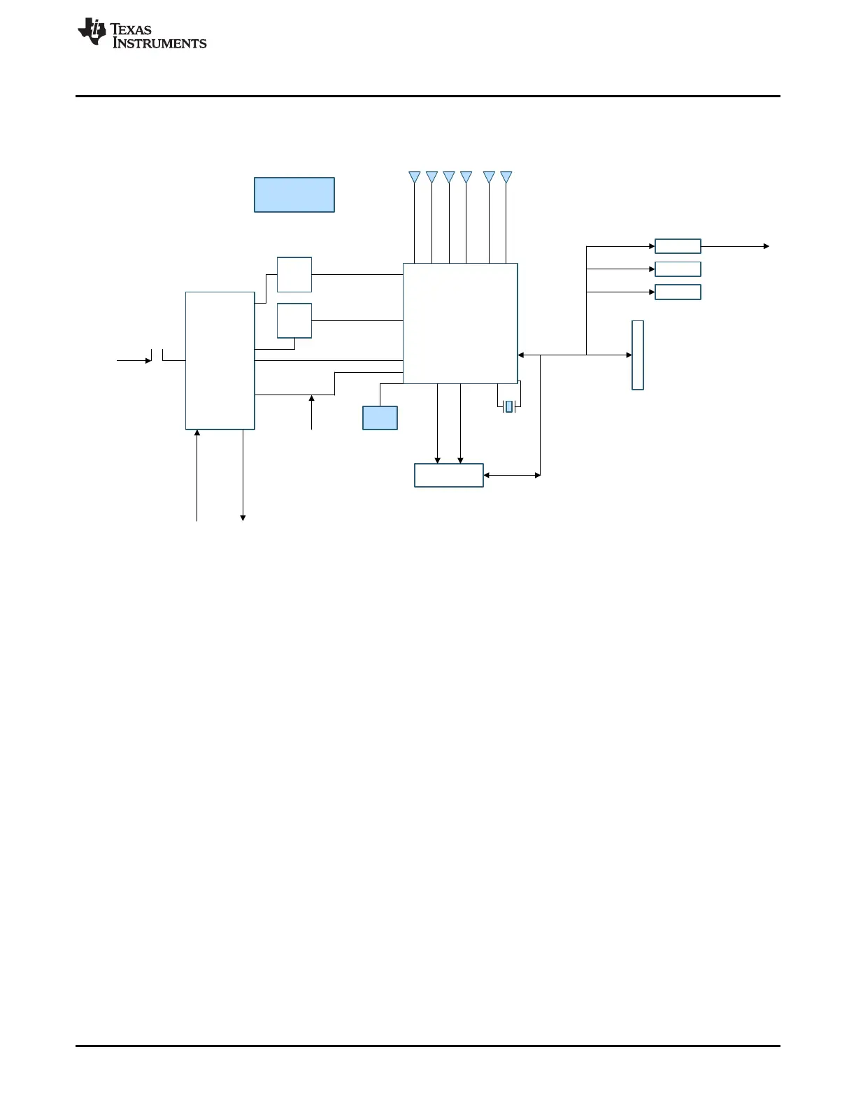
2.1 Block Diagram
Figure 3 shows the block diagram.
Figure 3. Block Diagram
 Loading...