26
MAINTENANCE
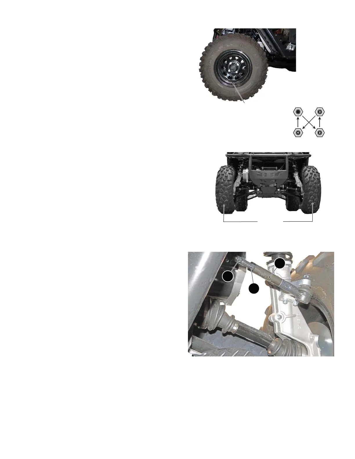
With the valve stem to the outside, mount the wheel onto the hub with lug nuts. Finger
tighten the lug nuts (1) in a ‘cross sequence’ pattern. Tighten the lug nuts to 65 to 75
ft. lbs. (88 to 101 Nm) torque in 20 ft. lbs. (27 Nm) increments following the ‘cross
sequence’ pattern.
Wheel Alignment
Driving over rough terrain may cause misalignment of the wheels. With four wheel indepen-
dent suspension both front and rear wheels may need to be aligned.
Park the vehicle on a level surface, set the front wheels straight ahead. Turn the key switch
to OFF and remove the key.
With the vehicle empty (no passengers or payload) measure the distance between the cen-
ter of the front set of tires. Measure both in front and behind the front tires, keeping the tape
measure parallel to the ground. The measurement behind the tires should be 1/8” to 1/4”
more than the measurement taken at the front of the tires to produce a toe-in condition.
Adjust both tie rods equally to obtain the correct toe-in. Hold tie rod (2) with an open
end wrench, loosen the jam nut (1) and turn the adjustment shaft (3) to move the
wheel in the desired direction.
Recheck the measurement at the front and at the rear of the front tires, if the 0” to 1/
8” toe-in has been achieved tighten the lock nut (1) on each tie rod.
Brakes
This vehicle is equipped with four wheel hydraulic disc brakes and a motor brake. Check the fluid level at intervals specified in the PERIODIC SERVICE
SCHEDULE; if fluid leaks are noticed or the brake pedal seems soft, check the fluid level immediately. If the brake pedal is soft, the brake system should be
bled to remove air from the brake lines. Refer to Bleeding Brakes on page 27 for procedure.
TOOLS
• Tape Measure • Open End Wrench, 12mm
• Open End Wrench, 17mm • Open End Wrench, 19mm
1
Cross Sequence
Tire style may vary
Valve Stem Cap
43 inches
1
3
2

 Loading...

