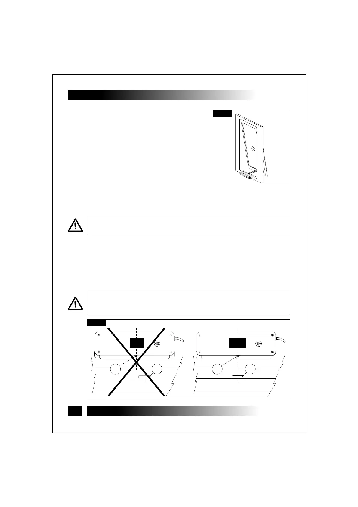
5.2- TOP HUNG WINDOWS
(Fig. 7 and 15÷24)
1) (par.3.7)
2) Fig.15-
3) Fig.16-
4) Fig.17-
5) Fig. 18-
6)
7) Fig.19-
8) Fig.20-
9)
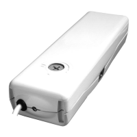
Open the package and extract the
various components;
With a pencil draw the centre line "X" of
the window frame;
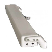
Select the following components:
bracket "S1", support "SA", two nuts "D1", two
screws "V1", heads "T1" and “T2";
Insert the two nuts "D1" on the support
"SA" and mount the head "T1" by fixing it using
screw "V1";
Cut out the adhesive template "DS" and apply it on the window frame
centring it on the previously drawn centre line "X";
With a suitable drill, create on the window frame holes having the related diameter,
given on the adhesive template "DS";
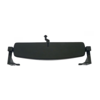
Mount the support "SA" on the fix window frame with the screws "V2"; Check
the perfect horizontal and vertical alignment with the window frame;
Mount the bracket "S1" on the movable window frame with the screws "V2";
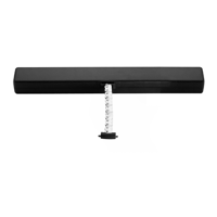
Mount the actuator on the support "SA", place the head "T2" and tighten the screw
"V1;
CAUTION: FOR NON-COPLANAR WINDOW FRAMES, IT IS NECESSARY TO CUT THE
TEMPLATE CONCERNED PART AND TO APPLY IT ON THE WINDOW FRAME PAYING
ATTENTION TO KEEP IT IN THE SAME REFERENCE POSITION.
VERIFY THAT THE CHAIN END "TC" IS ON THE SAME AXIS OF THE BRACKET "S1".
OTHERWISE, LOOSEN THE FIXING SCREWS AND POSITION IT CORRECTLY. WHEN THE
DEVICES ARE NOT COAXIAL, THIS MAY DAMAGE THE ACTUATOR AND THE WINDOW
FRAME (FIG. 8).
14
ACK4
5- IINSTALLATION
Fig.7
Fig.8
TC TC
S1 S1
NO
YES
INSTALLATION AND USE ISTRUCTIONS
VER.1.0
REV.11.05
 Loading...