15
INSTALLATION -5
ACK4
10) Fig.21-
Fig.22-
11) par.5.4
12) Fig.23-
13) Fig.24-
(Ref.A);
14) (Ref.A)
(Ref.B)
1) (par. 3.7)
2) Fig.25-
3) Fig.26-
4) Fig.27-
5) Fig.28-
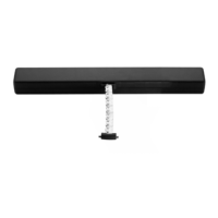
Mount the nut "D2" on the screw "V3" and then it on the chain ending "TC";
Connect the bracket "S1" to the screw "V3" by means of the pin "P";
Perform the electric connections according to the prescriptions of , as well as
with reference to the wiring diagram;
Act with a screwdriver or with a coin on the adjustment screw "VR", setting
the wished opening stroke (cm);
Perform a test of complete window frame opening and closing. After the
closing phase, verify that the chain end "TC" is completely returned in its seat
If the closing is right , fix the screw "V3" with the nut "D2" and the pin "P".
If the closing is not precise , perform the necessary adjustment of the screw
"V3" and of the nut "D2".
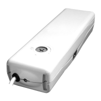
Open the package and extract the
various components;
With a pencil draw the centre line "Y" of
the window frame;
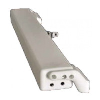
Select the following components:
bracket "S2" and "S3", support "SA", two nuts
"D1", two screws "V1", screw "V4", heads "T1"
and "T2";
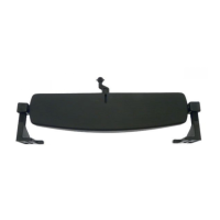
Insert the two nuts "D1" on the support
"SA" and mount the head "T2" by fixing it using
screw "V1";
Cut out the adhesive template "DV" and apply it on the window frame centring
it on the previously drawn centre line "Y";
CAUTION: VERIFY THAT THE SELECTED STROKE IS SOME CENTIMETRES LOWER
THAN THE STROKE EFFECTIVELY ALLOWED BY MECHANICAL LOCKS, COMPASS
STROKE LIMIT DEVICES, OR WING OPENINGHINDRANCES.
FOR A CORRECT ADJUSTMENT OF THE WINDOW FRAME CLOSING SEE THE
INDICATIONS GIVEN INPAR. 5.6.
CAUTION: FOR NON-COPLANAR WINDOW FRAMES, IT IS NECESSARY TO CUT THE
TEMPLATE CONCERNED PART AND TO APPLY IT ON THE WINDOW FRAME PAYING
ATTENTION TO KEEP IT IN THE SAME REFERENCE POSITION.
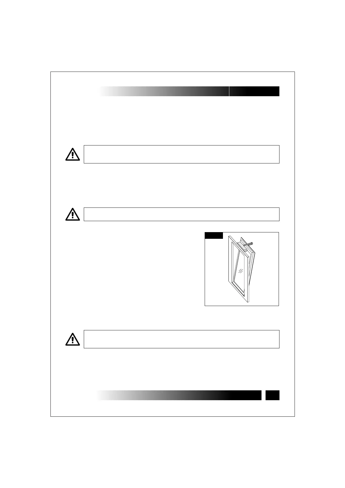
5.3- BOTTOM HUNG WINDOWS
(Fig.9 and 25÷34)
Fig.9
INSTALLATION AND USE ISTRUCTIONS
VER.1.0
REV.11.05

 Loading...