TOPVERT S1 Series
E-
6
Control Terminal Explanations (Available when an I/O card is installed)
Terminal
Symbols
Explanation on the Terminal Function Factory Default
MI1
Multi-function input selection 1
(3-wire STOP-designated terminal)
multi-step speed command 1
MI2 Multi-function input selection 2 multi-step speed command 2
R1A Multi-function relay 1 output contact (NO / a)
R1B Multi-function relay 1 output contact (NC / b)
R1C
Multi-function relay 1 output contact
– the common end
Resistive Load
5A(N.O.)/3A(N.C.) 240VAC
5A(N.O.)/3A(N.C.) 24VDC
Inductive Load
1.5A(N.O.)/0.5A(N.C.) 240VAC
1.5A(N.O.)/0.5A(N.C.) 24VDC
Refer to Pr.2-19, Pr.2-20
E Shield terminal
FWD FWD RUN-STOP command
REV REV RUN-STOP command
COM Digital/Analog control signal - the common end
+12V
Auxiliary reference power Reference point is
COM
+12V 20mA
AVI Multi-Function analog voltage command
The maximum operation
frequency corresponding to 0~+10V
ACI Multi-Function analog current command
The maximum operation
frequency corresponding to
4~20mA
Control signal wiring size: 18 AWG (0.75 mm
2
)
Analog control signal wire specification: 18 AWG (0.75 mm
2
), covered with shield twisted net.
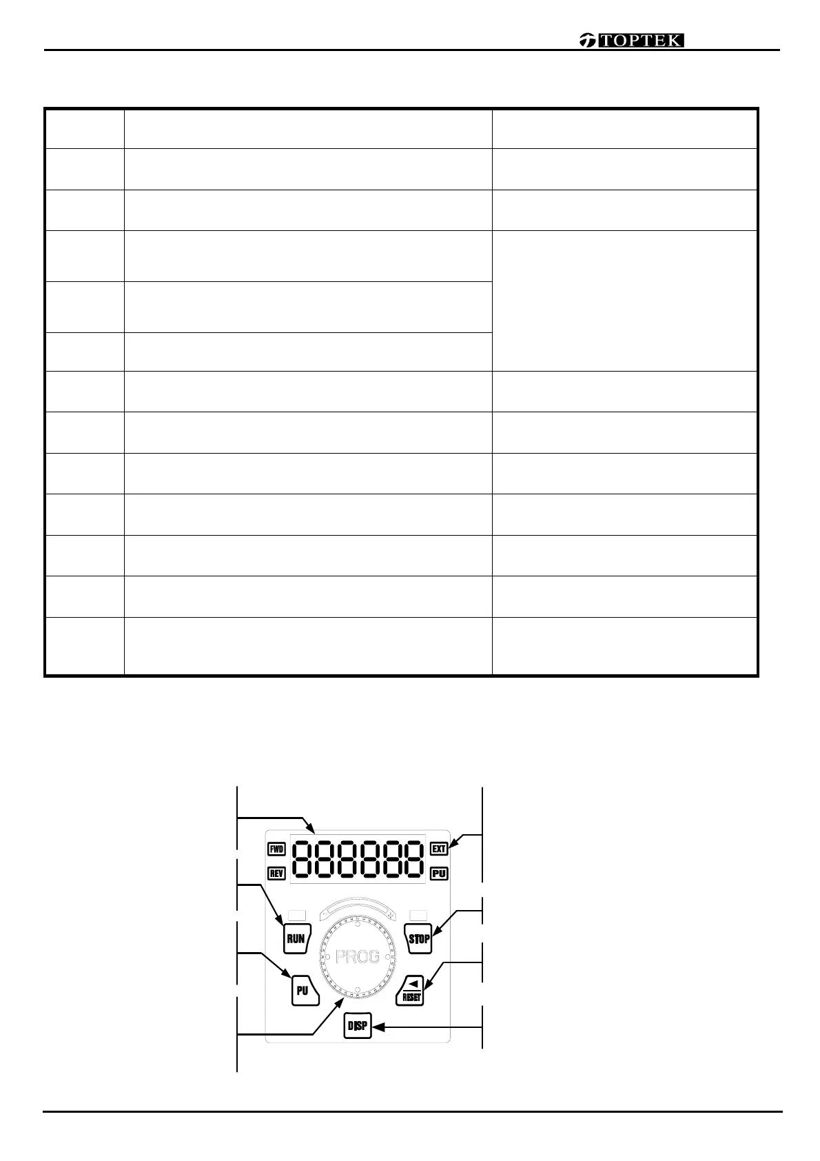
Description of the Digital Keypad
Main Display
Display the drive status such as frequency,
current, voltage,
parameter setting value
and alarm contents.
Programming Unit key
Enable the keypad. It can determine the
source of RUNSTOP
Programming Unit key
Enable the keypad. It can determine the
source of RUNSTOP
Display Selection key
Changes between different display mode.
STOP key
Status Display…… Display the driver's current status
When "PU" lights, RUN/STOP is controlled by panel.
When "PU" is dark, RUN/STOP is set by Pr0-19.
When "EXT" lights, frequency command is set by Pr0-18.
When "EXT" is dark,frequency command is controlled by panel.
When "REV" lights, Drive is in reverse operation.
When "FWD" lights, Drive is in forward operation.
Data modification/Program Dial
Rotate to modification for settings,
parameters
and output frequency adjustment.
Press to Read or Enter datas
Left /Reset key
Moves cursor to the Left / Reset errors.
 Loading...